Automatic clearance adjusting oil cylinder and hydraulic disc brake
A technology of automatic adjustment and clearance, applied in slack adjusters, brake types, brake actuators, etc., and can solve problems such as timely braking
- Summary
- Abstract
- Description
- Claims
- Application Information
AI Technical Summary
Problems solved by technology
Method used
Image
Examples
Embodiment 1
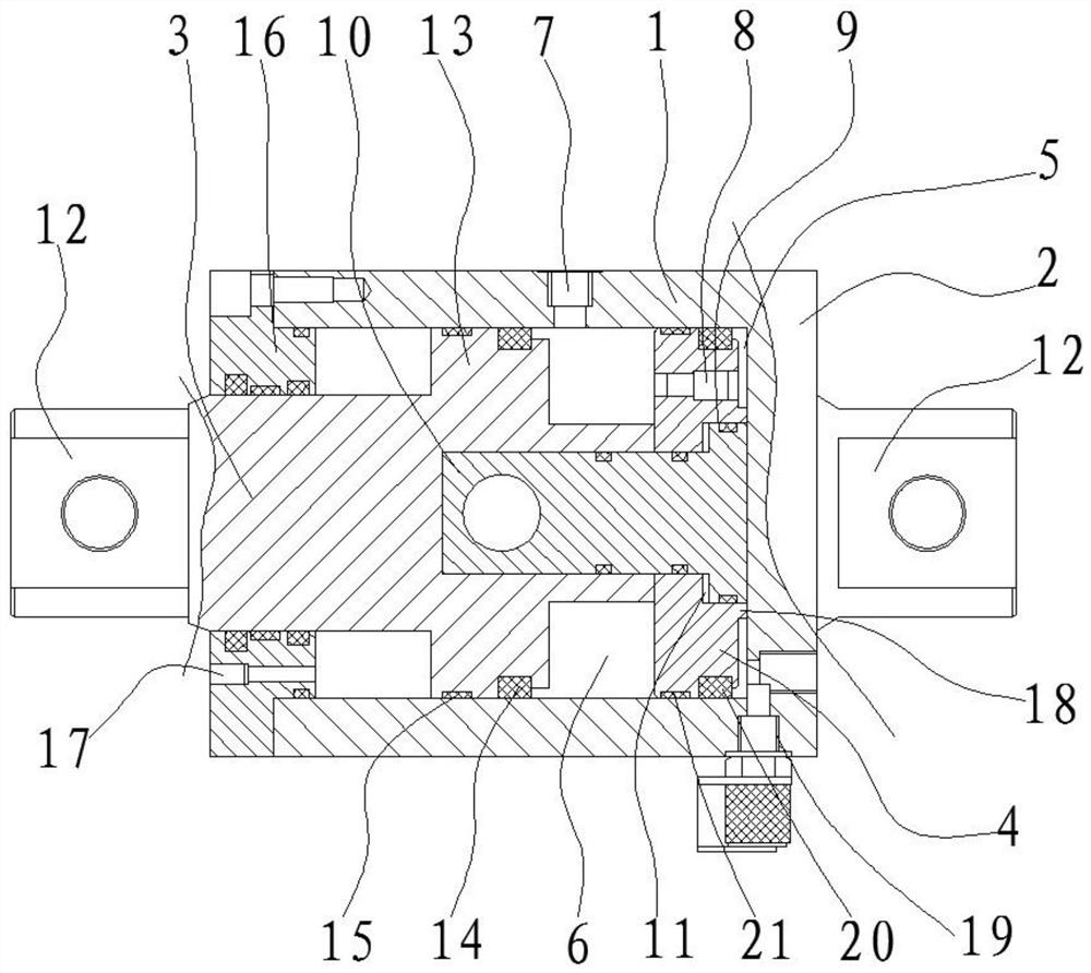
[0031] Such as figure 1 As shown, an embodiment of the present invention includes a cylinder body 1, one end of the cylinder body 1 is a closed end 2, and the other end is open, the inner cavity of the cylinder body 1 is cylindrical, and the inner cavity of the cylinder body 1 is A main piston 3 and a compensating piston 4 are provided, the main piston 3 is in sealing sliding connection with the inner wall of the cylinder body 1, and the outer peripheral wall of the compensating piston 4 is in sliding sealing connection with the inner wall of the cylinder body 1, in order to ensure the main The smoothness and tightness of the movement of the piston 3 and the compensation piston 4, the inner wall of the cylinder body 1 is a smooth surface, the compensation piston 4 is arranged between the main piston 3 and the inner wall of the closed end 2, the A compensation oil chamber 5 is provided between the compensation piston 4 and the inner wall of the closed end 2, a brake oil chamber...
Embodiment 2
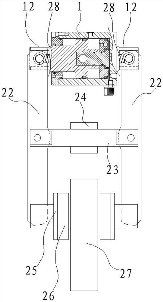
[0038] Such as figure 2 As shown, the second embodiment of the present invention discloses a hydraulic disc brake, including the above-mentioned automatic gap adjustment oil cylinder, caliper arm 22, support shaft 23, caliper frame 24, back plate 25, brake pad 26, brake Disc 27 and spring. The two cylinder ears 12 are respectively rotatably connected with one end of the two pincer arms 22 through a pin shaft, and the pin shafts on the two cylinder ears 12 are connected by a spring, and the two pincer arms 22 are connected by a spring. The middle part is connected to the two ends of the support shaft 23 through pin shaft rotation respectively. The support shaft 23 is fixed on the hydraulic disc brake device through the clamp frame 24, and the other ends of the two clamp arms 22 are connected with a pin shaft. The back plate 25 , the brake pads 26 are fixed on the back plate 25 , and the two brake pads 26 are respectively located on both sides of the brake disc 27 .
[0039] ...
PUM
 Abstract
Description
Claims
Application Information
 - R&D
- Intellectual Property
- Life Sciences
- Materials
- Tech Scout
- Unparalleled Data Quality
- Higher Quality Content
- 60% Fewer Hallucinations
Browse by: Latest US Patents, China's latest patents, Technical Efficacy Thesaurus, Application Domain, Technology Topic, Popular Technical Reports.
© 2025 PatSnap. All rights reserved.Legal|Privacy policy|Modern Slavery Act Transparency Statement|Sitemap|About US| Contact US: help@patsnap.com


