Operation table of machine tool

A technology of operating table and machine tool, which is applied in the direction of grinding machine parts, grinding frame, grinding machine bed, etc., can solve the problems of inconvenient and laborious operation, unfavorable quick processing of debris, small screwdriver width, etc., and achieves convenient operation. Effect

Active Publication Date: 2020-10-09
ZHEJIANG MEIRI INTELLIGENT EQUIP CO LTD
View PDF5 Cites 2 Cited by
  • Summary
  • Abstract
  • Description
  • Claims
  • Application Information

AI Technical Summary

Problems solved by technology

[0003] The surface of the current machine tool is equipped with a chute for fixing the processed object with the fixture. When grinding and cutting the parts, the debris falls on the surface of the working plate and the inside of the chute, affecting the sliding of the fixture. Now There is a way to clean the internal debris of the chute. Usually, the construction personnel use a screwdriver to clean the debris inside the chute. The cleaning speed is slow, and the chute of the parts that have not been cleaned for a long time is bonded to the surface of the work plate. The width of the screwdriver is small, and it is inconvenient and laborious to clean the debris at the chute. The loose debris in several chutes needs to be cleaned one by one with a brush, which is not conducive to the rapid processing of debris, and is not conducive to the fixture when reprocessing. placed again

Method used


Image

  • Operation table of machine tool
  • Operation table of machine tool
  • Operation table of machine tool

Examples


Embodiment Construction

[0023] In order to make the technical means, creative features, goals and effects achieved by the present invention easy to understand, the present invention will be further described below in conjunction with specific embodiments.

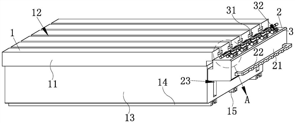
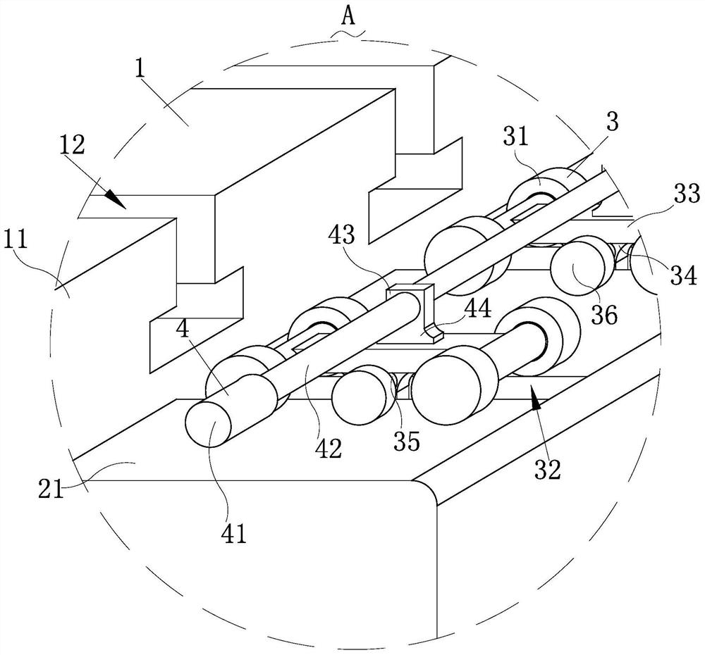
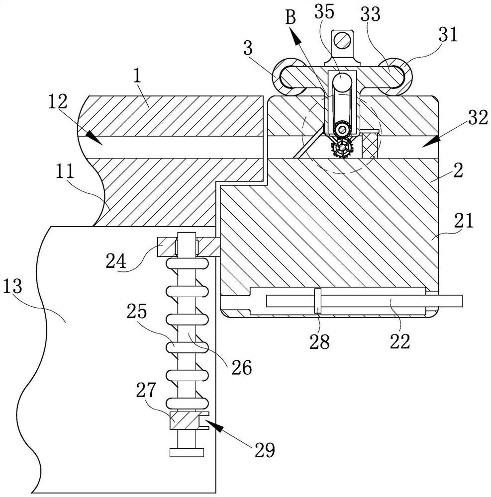
[0024] Such as Figure 1-Figure 6As shown, a machine tool operating table according to the present invention includes a placement mechanism 1, an installation mechanism 2, a driving mechanism 3, a pushing mechanism 4 and a cleaning mechanism 5, and is used to realize the placement mechanism 1 for placing parts to be processed. The mounting mechanism 2 is slidingly connected to one of the side walls, and the driving mechanism 3 is installed equidistantly on the surface of the mounting mechanism 2, and the distance between one end of several driving mechanisms 3 and the surface of the mounting mechanism 2 Rolling connection, and one end of several driving mechanisms 3 extends to the inside of the installation mechanism 2, several driving mechanisms ...


PUM


Abstract

The invention relates to the technical field of operation tables of machine tools, in particular to an operation table of a machine tool. The operation table comprises a placing mechanism, mounting mechanisms, driving mechanisms, pushing mechanisms and cleaning mechanisms. The side walls of the placing mechanism are slidably connected with the mounting mechanisms, the tops of the mounting mechanisms are equidistantly and slidably connected with the driving mechanisms, and after the mounting mechanisms are moved to the ends of the placing mechanism, the driving mechanisms are pushed, so that the cleaning mechanisms at the bottoms of the driving mechanisms clean up debris left during machining inside the placing mechanism, operation is convenient, and re-placement of a fixture is facilitated; the multiple driving mechanisms are connected through the pushing mechanisms, the pushing mechanisms are pulled away from one end of the mounting mechanisms while the debris inside the placing mechanism is cleaned up, the multiple cleaning mechanisms move simultaneously, and thus the debris inside the placing mechanism is cleaned up more quickly; and the mounting mechanisms located on the side walls of the placing mechanism can realizing limiting, so that moving of a machining mechanism is prevented from being affected during part machining.

Description

technical field [0001] The invention relates to the technical field of machine tool consoles, in particular to a machine tool console. Background technique [0002] A machine tool refers to a machine that manufactures a machine, also known as a machine tool or a tool machine, and is customarily referred to as a machine tool. Generally divided into metal cutting machine tools, forging machine tools and woodworking machine tools. There are many ways to process mechanical parts in modern machinery manufacturing: in addition to cutting, there are also casting, forging, welding, stamping, extrusion, etc. The cutting method is used on the machine tool for final processing. The machine tool work plate is used to place the objects to be processed, provide placement and support for the processed objects, and is usually made of heavy steel. [0003] The surface of the current machine tool is equipped with a chute for fixing the processed object with the fixture. When grinding and cu...

Claims


Application Information

Patent Timeline
Patent Type & Authority Applications(China)
IPC IPC(8): B23Q11/00B08B1/00B23Q1/25B23Q3/18B24B41/02B24B41/06B24B41/00B24B55/06
CPCB08B1/002B08B1/005B08B1/006B23Q1/25B23Q3/18B23Q11/0042B24B41/00B24B41/02B24B41/06B24B55/06
Inventor 周福敬
Owner ZHEJIANG MEIRI INTELLIGENT EQUIP CO LTD
Why Eureka
Try Eureka