
Headlight for vehicle

A technology for searchlights and vehicles, applied to headlights, vehicle components, lighting devices, etc., can solve problems such as complex structures, achieve the effects of reduced quantity and cost, improved uniformity, and improved maneuverability

Active Publication Date: 2020-03-31
VOLKSWAGEN AG
View PDF7 Cites 0 Cited by
  • Summary
  • Abstract
  • Description
  • Claims
  • Application Information

AI Technical Summary

Problems solved by technology

[0004] However, it turned out to be disadvantageous for the known floodlights that their construction was rather complex and that the uniformity of the light function was from the inner area of ​​the illuminated area towards the outer area (by targeting shading to make it visible or invisible) drops

Method used


Image

  • Headlight for vehicle
  • Headlight for vehicle
  • Headlight for vehicle

Examples


Embodiment Construction

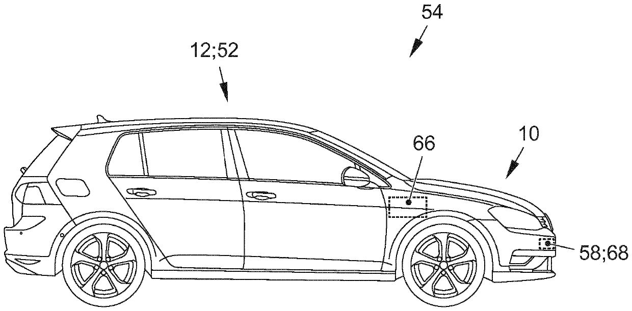
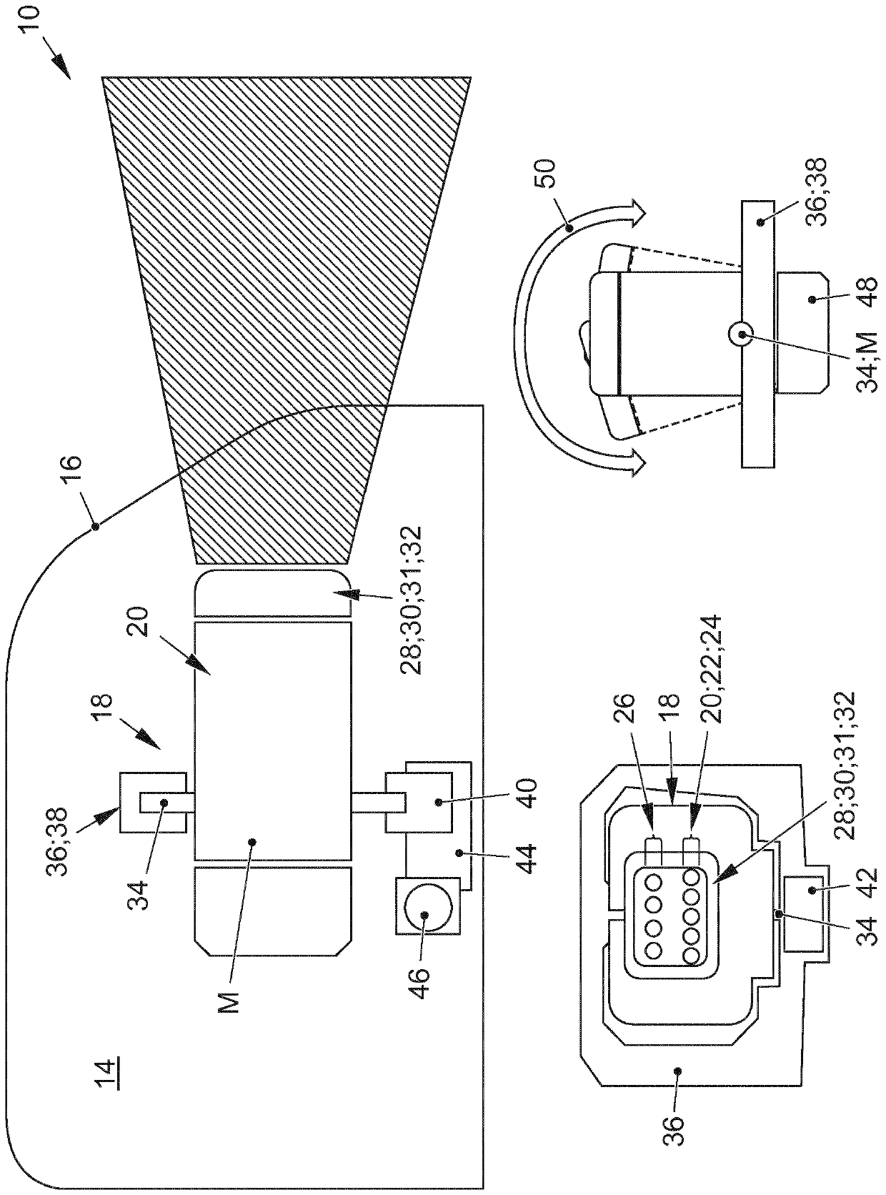
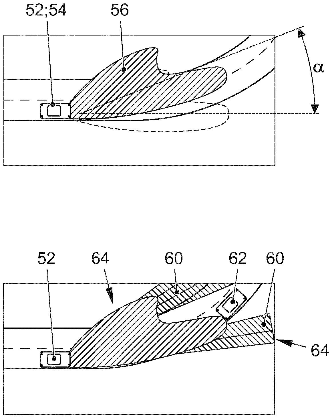
[0028] figure 1 Schematically shows a vehicle 12 according to the invention (see image 3 ) structure of the searchlight 10. Shown here is only the housing 14 of the headlight 10 , which is closed in the front region by a disc 16 . A light module 18 is arranged in the housing 14 . The light module 18 includes a matrix 20 of light emitting devices. exist figure 1Shown on the left in the lower part of , the luminous means matrix 20 comprises a plurality of individually actuatable luminous means 22 . The individually controllable luminous means 22 are light emitting diodes 24 in the present example. It can be seen that the light module 18 includes a row with light-emitting diodes 24 in the lower region. Further luminous means 26 are arranged above the luminous means matrix 20 . It forms a further row above the matrix 20 of light emitting devices. The matrix of luminous means 20 is used to generate a high beam 60 which can be activated segment by segment. For this purpose...


PUM


Abstract

The invention relates to a headlight (10), to a lighting system (54) and to a motor vehicle (52) having the headlight (10), wherein the headlight (10) combines a full beam matrix (20) and a dipped light in a common pivotable lighting module (18).

Description

technical field [0001] The invention relates to a searchlight for a vehicle according to the preamble of claim 1 , a lighting system according to the preamble of claim 7 and a motor vehicle according to the preamble of claim 11 . Background technique [0002] In the field of vehicles, such as motor vehicles, safety technology is of particular importance for searchlights. Light functions such as the basic light distribution (Grundlichtverteilung) or low beam (Abblendlicht) and high beam (Fernlicht) must meet high requirements here, especially with regard to their light-dark boundary, illuminated area (Ausleuchtungsbereich), intensity and uniformity. [0003] Adaptive light functions, such as adaptive turn indicators, are also increasingly being used. Conventionally, in a lighted area such as a low beam, for example, in the case of a left turn, the area at the right edge of the illuminated area is covered and the area at the left edge is additionally released by unmasking. ...

Claims


Application Information

Patent Timeline
Patent Type & Authority Applications(China)
IPC IPC(8): B60Q1/12B60Q1/14F21S41/63F21S41/663F21W102/145F21W102/13F21W102/19
CPCB60Q1/122B60Q1/143B60Q2300/056B60Q2300/41F21S41/635F21S41/663F21W2102/145F21W2102/13F21S41/151F21W2102/19B60Q1/076F21Y2115/10F21S41/153F21S41/657F21S45/47B60Q1/068
Inventor A.蒂尔I.奥帕斯卡C.洛泽M.塔姆
Owner VOLKSWAGEN AG
Learn More