A contact-free auxiliary device for quantitative cutting of wood boards

An auxiliary device and contact-free technology, which is applied in the direction of sawing components, sawing equipment, wood processing equipment, etc., can solve the problems of workers' waist injuries, wood cutting angle deviation, time wasting, etc., to save time and avoid injuries Effect

Active Publication Date: 2021-08-13
江苏金城建设有限公司
View PDF5 Cites 0 Cited by
  • Summary
  • Abstract
  • Description
  • Claims
  • Application Information

AI Technical Summary

Problems solved by technology

[0005] In order to overcome the fact that the metal frame cannot play a good guiding role, it is easy to cause the cutting angle of the board to shift, and it will cause damage to the waist of the worker after a long time. Moreover, it is necessary to use a scale to mark the cutting length on the board before cutting, which is a waste of time. Disadvantages, the technical problem to be solved is: to provide a non-contact quantitative cutting auxiliary device for wood boards that can prevent the board from being cut crookedly, avoid damage to the worker's waist, and save time

Method used


Image

  • A contact-free auxiliary device for quantitative cutting of wood boards
  • A contact-free auxiliary device for quantitative cutting of wood boards
  • A contact-free auxiliary device for quantitative cutting of wood boards

Examples


Embodiment approach 1

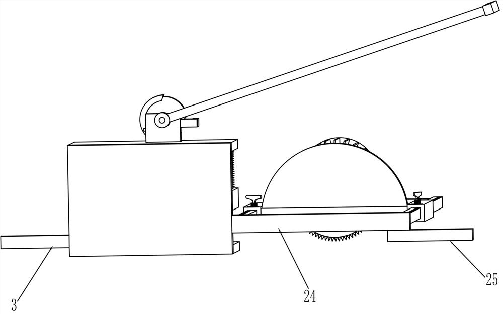
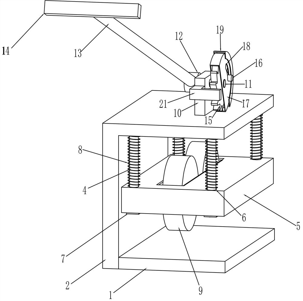
[0022] A non-contact auxiliary device for quantitative cutting of wood boards, see figure 1 , figure 2 and Figure 5 , including a placement board 1, a support board 2, a guide assembly, a push assembly, a mounting rod 24, a support rod 26, a scale 27, a second connecting block 28, a fixed-length assembly and a cutting machine 36, and the right side of the placement board 1 is provided with a support Plate 2, the support plate 2 is provided with a guide assembly, the guide assembly is provided with a push assembly, the installation rod 24 is fixed on the rear side of the support plate 2, and the left side of the installation rod 24 is symmetrically provided with a support rod 26. Two support rods 26 Scale 27 is provided on the top, and the second connection block 28 is connected between the two support rods 26. The two support rods 26 are slidably provided with a fixed-length assembly, and the fixed-length assembly is provided with a cutting machine 36, which is used for the...

Embodiment approach 2

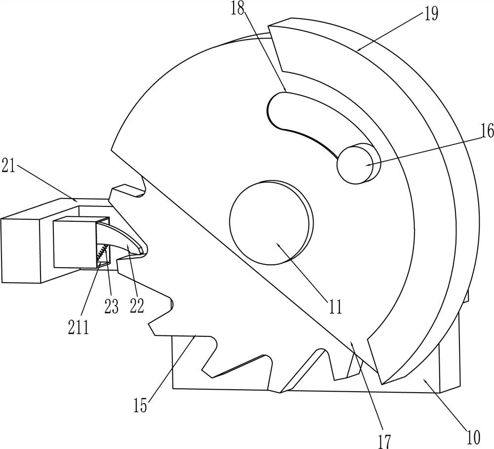
[0025] On the basis of embodiment 1, refer to Figure 1-6 , the guide assembly includes a first guide block 3, a vertical rod 4, a lifting plate 5, a block 7, a first elastic member 8, a roller 9 and a second guide block 25, and the front side of the support plate 2 is provided with a first guide block 3 , the top of the support plate 2 is symmetrically provided with a vertical bar 4 front and back, and the bottom of the vertical bar 4 is provided with a lifting plate 5, and the lifting plate 5 is provided with a through hole 6 symmetrically front and back, the vertical bar 4 passes through the through hole 6, and the bottom of the vertical bar 4 There are stoppers 7, and the four corners of the inner top of the support plate 2 are provided with first elastic parts 8, the first elastic parts 8 are connected with the lifting plate 5, the first elastic parts 8 are wound on the vertical rod 4, and the middle part of the lifting plate 5 rotates The formula is provided with two rol...


PUM


Abstract

The invention relates to an auxiliary device, in particular to a non-contact auxiliary device for quantitatively cutting wood boards. The technical problem to be solved is how to provide a non-contact auxiliary device for quantitatively cutting wood boards that can prevent the boards from being cut crookedly, avoid damage to the waist of workers, and save time. A non-contact auxiliary device for quantitative cutting of wood boards, including a placement board, a support board, a guide assembly, etc.; a support board is provided on the right side of the placement board, and a guide assembly is provided on the support board. The invention can guide the cutting machine through the guide assembly, so that the cutting machine can move in a straight line, thereby avoiding the board from being cut crookedly, and by pushing the assembly, the height of the handle can be adjusted according to the height of the worker, thus eliminating the need for The worker bends down to avoid injury to the worker's waist, and the length-fixing component can quickly determine the length of the plank cut, which can save time.

Description

technical field [0001] The invention relates to an auxiliary device, in particular to a non-contact auxiliary device for quantitatively cutting wood boards. Background technique [0002] Wooden boards are wooden boards made of complete wood. These boards are durable, natural in texture and clear in structure. They are the first choice for decoration. Wooden boards can also be used to make furniture. In the process of furniture processing, wood boards need to be cut into long strips . [0003] At present, workers generally install the hand-held cutting machine on a rectangular metal frame, hold one side of the metal frame with one hand, and hold the hand-held cutting machine with the other hand to push forward to cut the plank, so that when the cutting starts , the metal frame cannot play a very good guiding role, and it is easy to cause the cutting angle of the wood to deviate. When cutting, it is necessary to bend forward and push forward. After a long time, it will cause ...

Claims


Application Information

Patent Timeline
Patent Type & Authority Patents(China)
IPC IPC(8): B27C5/02B27C5/04
CPCB27C5/02B27C5/04
Inventor 不公告发明人
Owner 江苏金城建设有限公司
Why Eureka
Try Eureka