Flexible circuit board laser cutting equipment

A flexible circuit board and laser cutting technology, which is applied in laser welding equipment, welding equipment, metal processing equipment, etc., can solve the problems of low winding efficiency and irregularity, reduce the workload of workers, prevent winding and overlapping, and improve The effect of production efficiency

Active Publication Date: 2022-01-28
苏州开密科智能装备科技有限公司
View PDF10 Cites 2 Cited by
  • Summary
  • Abstract
  • Description
  • Claims
  • Application Information

AI Technical Summary

Problems solved by technology

[0004] In order to overcome the shortcomings of low efficiency of manual feeding and winding, and the flexible circuit boards of strip lights after cutting stick together, or are not neat, and cannot prevent them from being entangled and overlapped, the invention provides a laser cutting equipment for flexible circuit boards

Method used


Image

  • Flexible circuit board laser cutting equipment
  • Flexible circuit board laser cutting equipment
  • Flexible circuit board laser cutting equipment

Examples


Embodiment 1

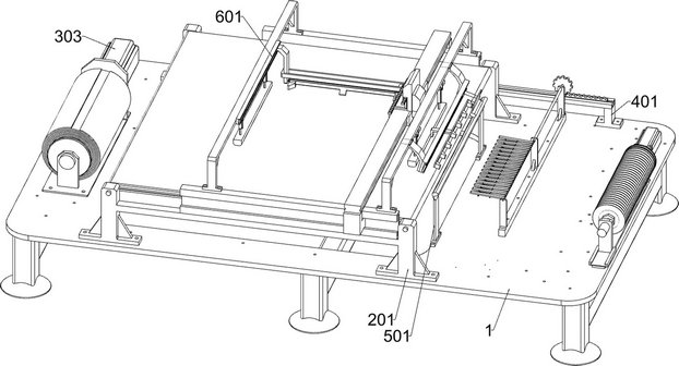
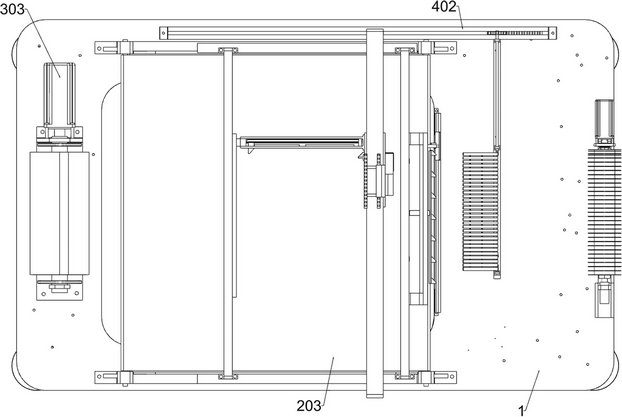
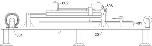
[0040] A flexible circuit board laser cutting equipment, such as Figure 1-12 As shown, it includes a fixed frame 1, a laser cutting unit, a transmission and winding unit, a carding unit and a grid pressing unit; The transmission and winding unit is installed on the left and right sides of the surface; the right side of the laser cutting unit is connected to the carding unit with a flexible circuit board; the lower side of the carding unit is connected to the fixing frame 1; And the grid pressing unit is located on the left of the carding unit; the lower side of the grid pressing unit is connected to the fixing frame 1 .

[0041] The laser cutting unit includes a first fixed plate 201, a second fixed plate 202, an electric conveyor belt 203, a first slide rail 204, a U-shaped frame 205, a first driving member 206, a first pressing plate 207, a second driving member 208, a first Two slide rails 209, a third driver 2010 and a laser cutting instrument 2011; the first fixed plate...

Embodiment 2

[0050] On the basis of Example 1, such as figure 1 and Figure 13-16 As shown, a detection unit is also included, and a detection unit is installed between the third driving member 2010 and the U-shaped frame 205 on the left, and the detection unit includes a sixth slide rail 601, a second L-shaped slide plate 602, a second connection Plate 603, separation dial 604, the third wedge-shaped block 605, the seventh fixed plate 606, the fourth wedge-shaped block 607, square plate 608 and detection probe 609; Six slide rails 601; the sixth slide rail 601 is slidingly connected with a second L-shaped slide plate 602; the lower part of the right side of the second L-shaped slide plate 602 is bolt-connected with a second connecting plate 603; the lower part of the right side of the second L-shaped slide plate 602 The separation dial 604 is connected with the torsion spring rotating shaft, and the separation dial 604 is located in front of the second connecting plate 603, and the front...


PUM


Abstract

The invention relates to the field of laser cutting, in particular to flexible circuit board laser cutting equipment. The technical problems that manual feeding and winding efficiency is low, cut strip-shaped lamp strip flexible circuit boards are bonded together or are not neat, and winding and overlapping of the strip-shaped lamp strip flexible circuit boards cannot be prevented are solved. According to the technical scheme, the flexible circuit board laser cutting equipment comprises a fixing frame, a laser cutting unit, a conveying and winding unit, a carding unit and the like; a laser cutting unit used for laser cutting of the lamp strip flexible circuit board is installed on the upper surface of the fixing frame. The left side and the right side of the upper surface of the fixing frame are provided with conveying and rolling units used for conveying and rolling the lamp strip flexible circuit board. The right side of the laser cutting unit is connected with a carding unit used for carding the cut lamp strip flexible circuit board. The conveying and rolling units are designed, the functions of automatic feeding and disc dividing and winding of the lamp strip flexible circuit board are achieved, the production efficiency is effectively improved, and the workload of workers is reduced.

Description

technical field [0001] The invention relates to the field of laser cutting, in particular to a laser cutting device for a flexible circuit board. Background technique [0002] In the existing technology, when cutting the flexible circuit board of the light strip, it is impossible to realize automatic feeding and rewinding, all of which require manual operation, resulting in low production efficiency; The part is in a straightened and wrinkle-free state, which leads to the sticking of the flexible circuit board of the strip light strip after cutting, and the problem of irregularity; [0003] Further, while cutting, it is impossible to separate the cut flexible circuit board of the strip light strip, resulting in winding and overlapping between the flexible circuit boards of the strip light strip, causing damage to the flexible circuit board of the strip light strip, And it is not easy to roll up. Contents of the invention [0004] In order to overcome the shortcomings of ...

Claims


Application Information

Patent Timeline
Patent Type & Authority Applications(China)
IPC IPC(8): B23K26/38B23K26/70
CPCB23K26/38B23K26/702
Inventor 刘冉冉徐现强李龙芳
Owner 苏州开密科智能装备科技有限公司
Why Eureka
Try Eureka