
Deceleration strip for bridges and roads

A technology of speed bumps and roads, which is applied in the field of transportation facilities, can solve problems such as unfavorable drivers driving safely, affecting driver experience, etc., and achieve the effect of avoiding bumps

Inactive Publication Date: 2020-04-03
王敏帆
View PDF0 Cites 0 Cited by
  • Summary
  • Abstract
  • Description
  • Claims
  • Application Information

AI Technical Summary

Problems solved by technology

However, the speed reduction belt in the prior art will have a sense of bumps no matter whether it is passing at high speed or passing at low speed, and this is undoubtedly a bad experience for drivers who obey traffic rules and drive at low speed, but they will still bump when driving at low speed. Affects the driver's experience and is not conducive to cultivating the driver's awareness of safe driving

Method used


Image

  • Deceleration strip for bridges and roads
  • Deceleration strip for bridges and roads
  • Deceleration strip for bridges and roads

Examples


Embodiment 1

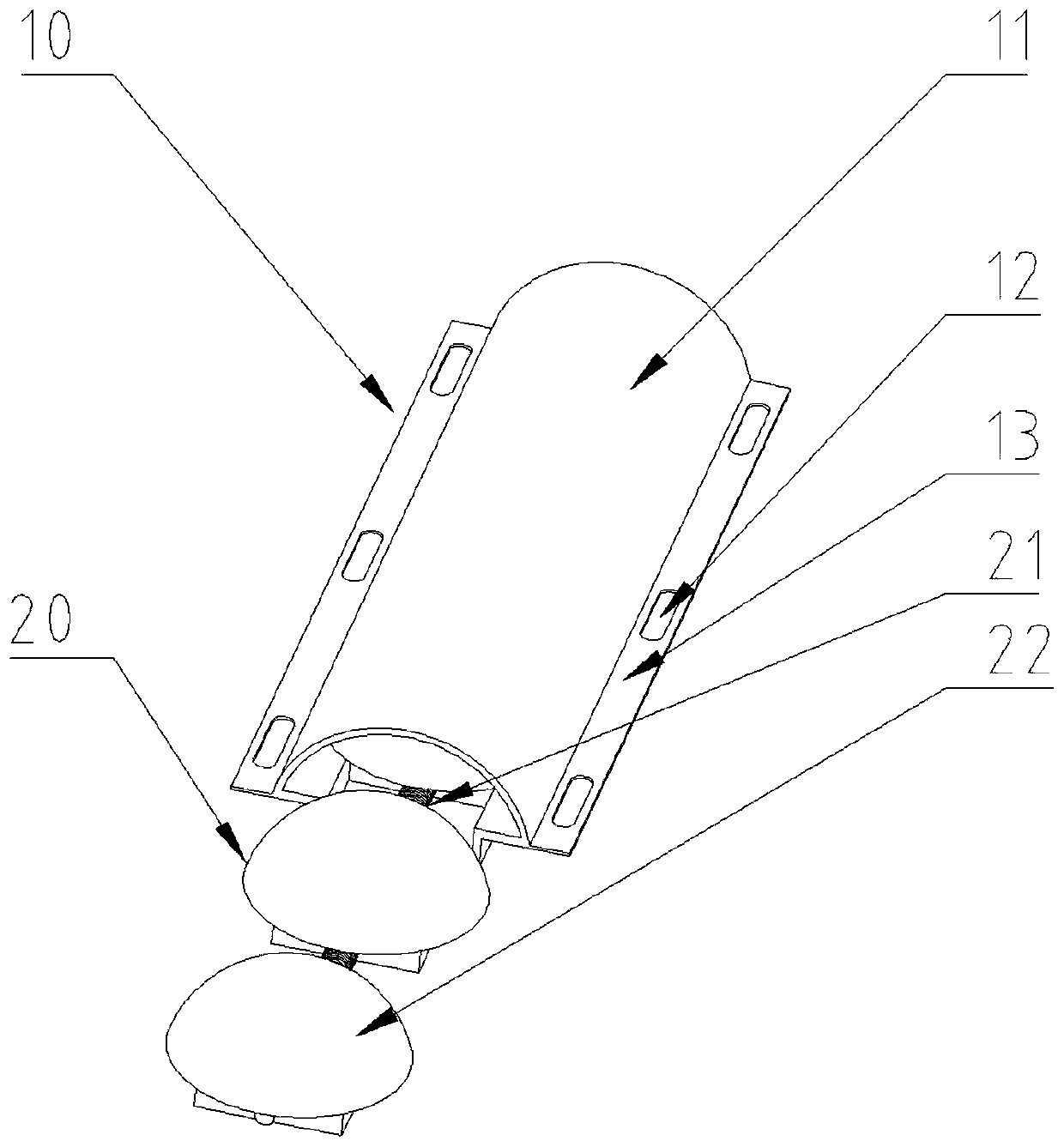
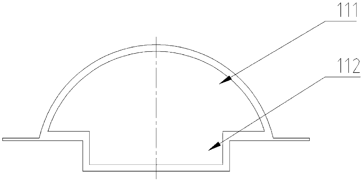
[0019] see Figure 1-3 , a deceleration belt for bridge roads, including a protection mechanism 10 and a movable mechanism 20, the protection mechanism 10 includes a housing 11, a mounting hole 12 and a mounting plate 13, and the housing 11 includes a housing upper end 111 and a housing lower end 112. The upper end 111 of the housing is in the shape of a circular arc. Through the structure of the transition between the arc and the ground, in addition to making it easier for vehicles to pass by, it also makes the movable block that matches it in the upper end 111 of the housing The space between the upper ends 222 is more likely to be squeezed away by the wheels of the vehicle. At the same time, the arc structure can also minimize the damage to the tires under high-speed impact, especially in the hot summer. The temperature rises and expands, causing the pressure in the tire to rise. At this time, if a sharp object is encountered during high-speed operation and local stress co...

Embodiment 2

[0027] The difference between this embodiment and Embodiment 1 is that the material of the lower end 112 of the housing is stainless steel, and there are no installation holes 12 on both sides of the lower end 112 of the housing. The example is poured together with the concrete.

[0028] The working principle of the present invention is:

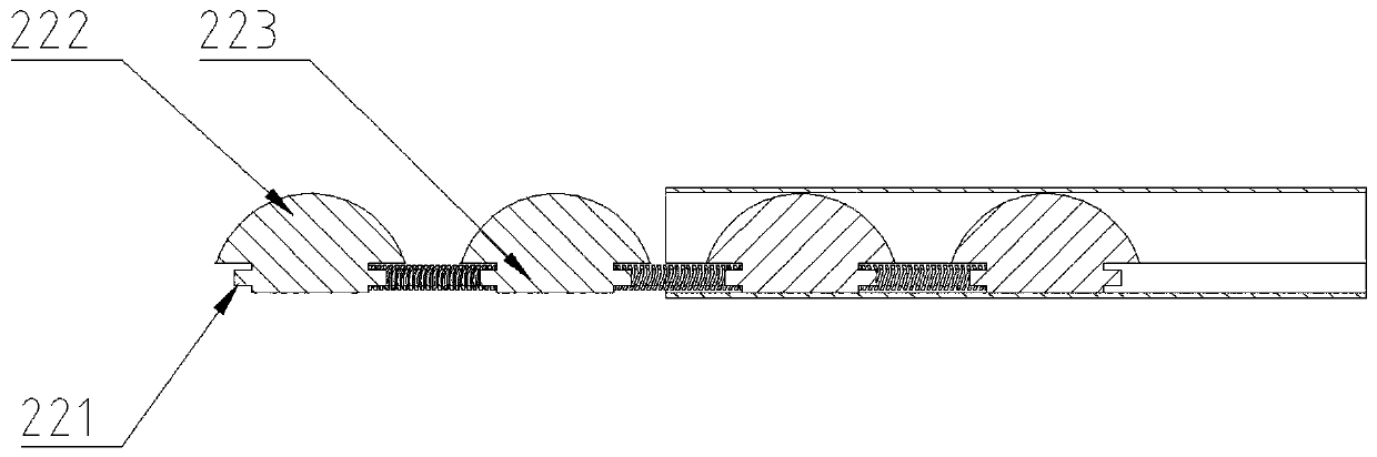
[0029]The present invention protects the movable mechanism 20 from being polluted by rainwater and dust through the housing 11 made of flexible material, and the movable block 22 can slide in the lower end 112 of the housing, when the automobile passes the deceleration belt at a slow speed The tires of the automobile squeeze the movable blocks 22 away from each other, so that the tires are in direct contact with the ground, and there is no bumpy feeling when driving. After passing by, the movable blocks 22 return to their original positions under the action of the spring 21. And when automobile passes by at a high speed, there is no time to...


PUM


Abstract

The invention discloses a deceleration strip for bridges and roads. The deceleration strip comprises a protection mechanism and a movable mechanism, the protection mechanism comprises a shell, a mounting hole and a mounting plate; the movable mechanism comprises a movable block, a shell upper end and a shell lower end. According to the invention, the shell is made of a deformable flexible material; when a tire of a vehicle is pressed, the tire deforms, the upper end of the movable block is arc-shaped, the movable block IS connected with the adjacent movable blocks through springs; when the vehicle passes through at a low speed, after the tire presses the shell and deforms, the movable block can be pushed to move; therefore, the movable blocks are pushed to two sides of the tire; at the moment, no obstacle exists below the tire, then the phenomenon of bumping when the vehicle passes through the deceleration strip at a low speed is avoided, and when the vehicle passes through the deceleration strip at a high speed, the movable blocks do not have enough time to move to the two sides of the tire, so that the obstacles such as the movable blocks exist below the tire, bumping feeling isbrought to a driver, and the driver is reminded to slow down.

Description

technical field [0001] The invention relates to the field of traffic facilities, in particular to a deceleration belt for bridges and roads. Background technique [0002] With the improvement of the economic level and people's living standards, people's requirements for the quality of life and travel safety are getting higher and higher. At present, private cars are the most used ones, and the current situation that almost every family has a car has caused vehicles on the road to a lot of. For the sake of speed limit and reducing traffic accidents, the setting of speed bumps is essential. At present, speed bumps are installed on many roads, such as the entrance of the community, the exit section of the school, and the turning section of the high-speed road. The density of speed bumps is generally higher. However, the speed reduction belt in the prior art will have a sense of bumps no matter whether it is passing at high speed or passing at low speed, and this is undoubtedl...

Claims


Application Information

Patent Timeline
IPC IPC(8): E01F9/529
CPCE01F9/529
Inventor 王敏帆
Owner 王敏帆
Features
  • Generate Ideas
  • Intellectual Property
  • Life Sciences
  • Materials
  • Tech Scout
  • Unparalleled Data Quality
  • Higher Quality Content
  • 60% Fewer Hallucinations
Learn More