

Vehicle headlight
A technology for headlights and vehicles, which is applied in the direction of headlights, vehicle parts, lighting and heating equipment, etc. It can solve problems such as optical unit configuration that is not mentioned, and achieve the effects of preventing glare, uniform overall brightness, and good appearance
- Summary
- Abstract
- Description
- Claims
- Application Information
AI Technical Summary
Problems solved by technology
Method used
Image

Examples
no. 1 approach
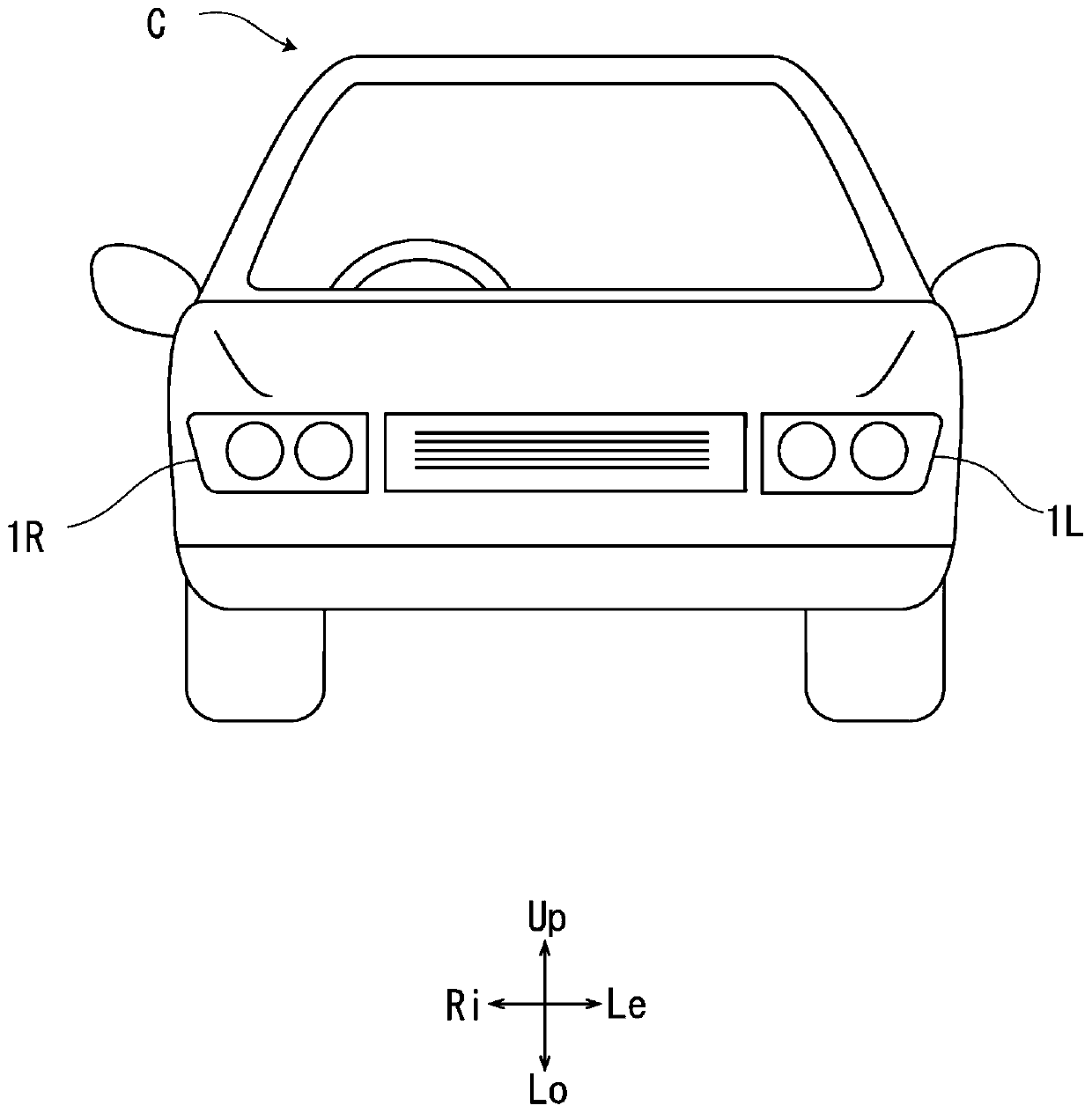
[0057] figure 1 The vehicle C shown has a right headlight 1R and a left headlight 1L. The right headlight 1R and the left headlight 1L are a pair of left and right vehicle headlights. In the present embodiment, the vehicle C is a right steering wheel specification, and a right headlight 1R is mounted on the right side of the vehicle C, that is, the driver's seat side, and a left headlight 1L is mounted on the left side of the vehicle C, that is, the passenger's seat side.
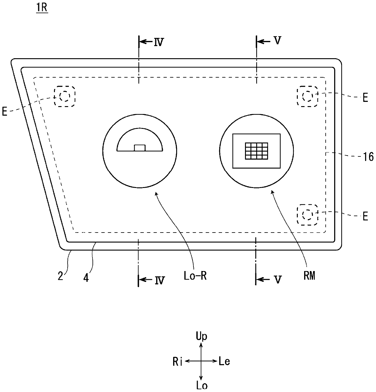
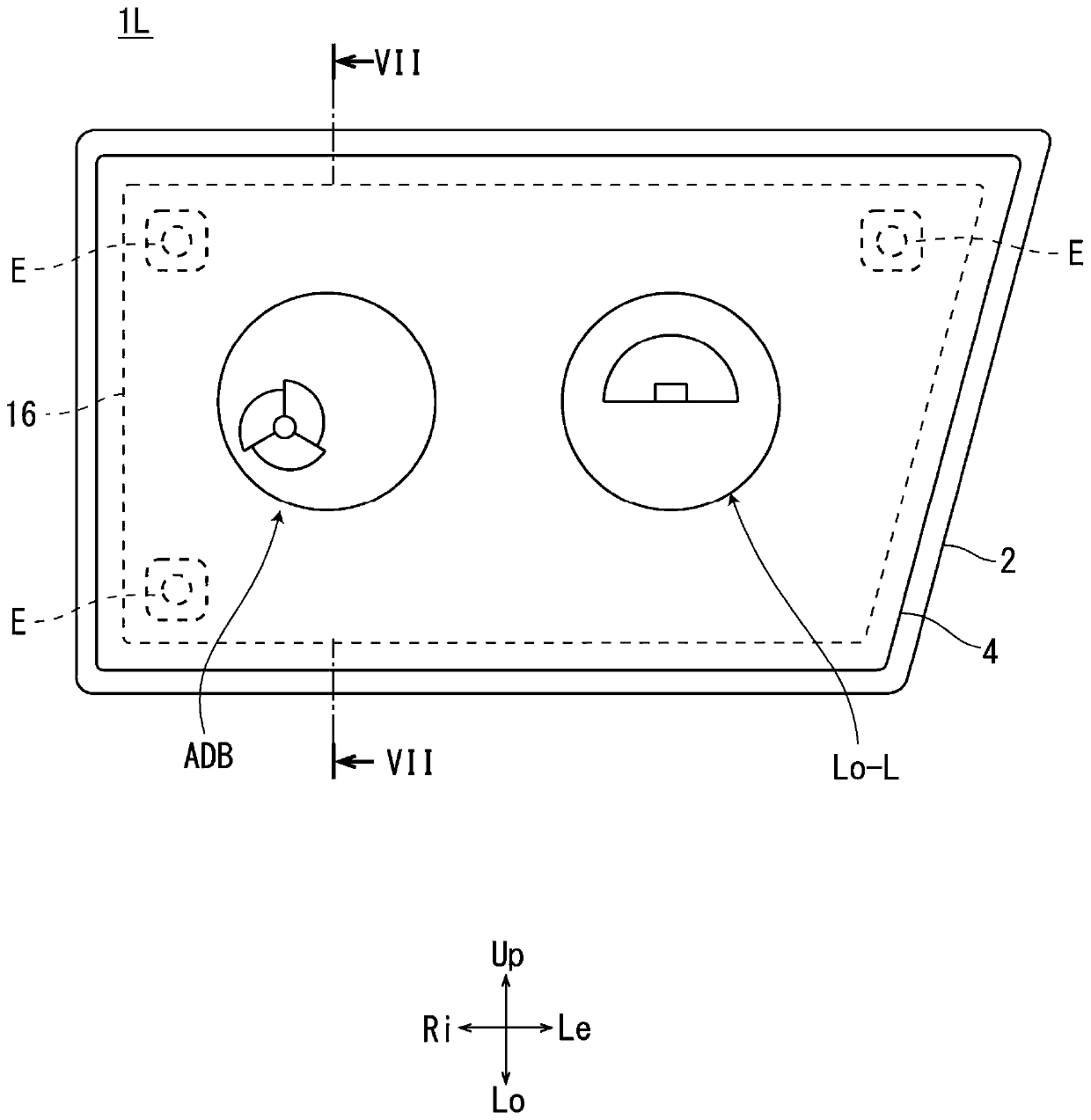
[0058] Such as figure 2 and image 3 As shown, the right headlight 1R and the left headlight 1L respectively include: a lamp body 2 having an opening in front of the vehicle C, and a front lamp made of translucent resin or glass mounted on the opening of the lamp body 2 . Surface cover 4. A lamp chamber is formed inside the lamp body 2 and the front cover 4 .
[0059] In the lamp housing of the right headlamp 1R, the pattern rendering optical unit RM and the low beam optical unit Lo-R are housed in th...
no. 2 approach
[0133] Next, a second embodiment will be described. The same symbols are assigned to the same structures as those in the first embodiment, and explanations thereof will be omitted.
[0134] Figure 14 It is a front view of the right headlamp 101R of the second embodiment, Figure 15 It is a front view of the left headlight 101L of the second embodiment.
[0135] Unlike the first embodiment, the right headlight 101R and the left headlight 101L each have three optical units housed in the lamp housings.
[0136] In the lamp housing of the right headlamp 101R, a pattern drawing optical unit RM, a light distribution variable optical unit ADB-R, and a low beam optical unit Lo-R are housed in this order from the inside (left side) in the vehicle width direction. The light distribution variable optical unit ADB-L2, the light distribution variable optical unit ADB-L1, and the low beam optical unit Lo-L are housed in the lamp housing of the left headlamp 101L in order from the inside...
no. 3 approach
[0145] Next, a third embodiment will be described. The same symbols are assigned to the same configurations as those in the first embodiment, and description thereof will be omitted.
[0146] Figure 17 It is a front view of the right headlamp 201R of the third embodiment, Figure 18 It is a front view of the left headlight 201L of the third embodiment.
[0147] As in the second embodiment, three optical units are housed in each of the right headlight 201R and the left headlight 201L in lamp housings.
[0148] In the lamp housing of the right headlamp 201R, a pattern drawing optical unit RM-R, a variable light distribution optical unit ADB-R, and a low beam optical unit Lo-R are housed in this order from the inside (left side) in the vehicle width direction. In the lamp housing of the left headlamp 201L, the pattern drawing optical unit RM-L, the light distribution variable optical unit ADB-L, and the low beam optical unit Lo-L are housed in this order from the inside (righ...
PUM
 Abstract
Description
Claims
Application Information