
Heat pump heat exchange device of drying chamber

A technology for heat exchange devices and drying chambers, which is applied in heating devices, cleaning heat transfer devices, drying, etc., and can solve problems such as dehumidification of hot and humid air

Pending Publication Date: 2020-04-07
江门市康度仕电器科技有限公司
View PDF0 Cites 0 Cited by
  • Summary
  • Abstract
  • Description
  • Claims
  • Application Information

AI Technical Summary

Problems solved by technology

[0002] Drying operations are now widely used in industry and agriculture, especially in the agricultural field. The current drying room adopts a variety of drying methods and cannot accurately dehumidify the hot and humid air after heat exchange, and then dehumidify The hot and dry air is transported to the drying room for drying operation. In view of the existing technical defects, it is necessary to propose a new technical solution

Method used


Image

  • Heat pump heat exchange device of drying chamber

Examples


Embodiment Construction

[0015] The specific embodiments of the present invention will be further described below in conjunction with the accompanying drawings. It should be noted here that the descriptions of these embodiments are used to help understand the present invention, but are not intended to limit the present invention. In addition, the technical features involved in the various embodiments of the present invention described below may be combined with each other as long as they do not constitute a conflict with each other.

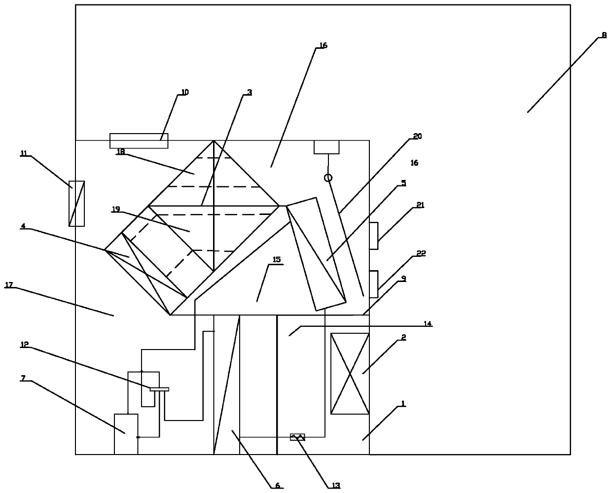
[0016] like figure 1 As shown, the present invention discloses a drying room heat pump heat exchange device, including a drying box 1, a blower fan 2, a sensible heat recovery device 3, an evaporator fan 4, an evaporator 5, a condenser 6 and a compressor 7, Blower fan 2 is installed on the bottom side wall of drying box 1, and blower fan 2 is in contact with the outside of drying chamber 8, and condenser 6 and compressor 7 are respectively installed in the drying chambe...


PUM


Abstract

The invention discloses a heat pump heat exchange device of a drying chamber. The device comprises a drying box, an air supply fan, a sensible heat recoverer, an evaporation fan, an evaporator, a condenser and a compressor; an air supply fan is mounted on the side wall of the bottom of the drying box; the air supply fan is in contact with the outside of the drying chamber; the condenser and the compressor are respectively arranged in the drying chamber adjacent to the air supply fan; a partition plate is mounted over the condenser and the air supply fan; and the sensible heat recoverer and theevaporator are obliquely installed at the two sides of the upper portion of the partition plate; the evaporation fan is installed at the bottom of the sensible heat recoverer; one corner of the evaporation fan is fixed to the partition plate; and an air inlet and a control air valve are arranged at the positions, corresponding to the sensible heat recoverer, of the upper portion and the side wallof the drying box correspondingly. According to the drying chamber heat pump heat exchange device, low-temperature damp and hot air in the drying chamber can be recycled, and the air is returned to the drying chamber to be subjected to secondary dehumidification after being subjected to accurate dehumidification through the heat exchange device.

Description

technical field [0001] The invention relates to a heat pump system, in particular to a heat pump heat exchange device for a drying chamber. Background technique [0002] Drying operations are now widely used in industry and agriculture, especially in the agricultural field. The current drying room adopts a variety of drying methods and cannot accurately dehumidify the hot and humid air after heat exchange, and then dehumidify The final hot and dry air is transported to the drying chamber for drying operation. In view of the existing technical defects, it is necessary to propose a new technical solution. Contents of the invention [0003] The technical problem to be solved by the present invention is to provide a heat pump heat exchange device for the drying chamber, which can recycle the low-temperature, hot and humid air in the drying chamber, and return it to the drying chamber for secondary dehumidification after being accurately dehumidified by the heat exchange device...

Claims


Application Information

Patent Timeline
Patent Type & Authority Applications(China)
IPC IPC(8): F26B9/06F26B21/00F26B23/00F26B25/00F26B25/12F28G9/00
CPCF26B9/06F26B21/001F26B23/004F26B25/00F26B25/12F28G9/00Y02P70/10
Inventor 赖辉盛
Owner 江门市康度仕电器科技有限公司
Learn More