
Numerical control machine tool feed shaft thermal error monitoring method based on digital twinning

A technology for CNC machine tools and feed shafts, which is applied in program control, computer control, general control systems, etc., and can solve the problems of insufficient monitoring capability of feed shaft thermal errors and failure to realize three-dimensional real-time visualization of the thermal deformation state of feed shafts. , to achieve the effect of real-time visual monitoring

Active Publication Date: 2020-04-07
DALIAN UNIV OF TECH
View PDF10 Cites 7 Cited by
  • Summary
  • Abstract
  • Description
  • Claims
  • Application Information

AI Technical Summary

Problems solved by technology

[0005] The present invention aims at the problem that the thermal error compensation of the feed shaft of the existing CNC machine tool fails to realize the three-dimensional real-time visualization of the thermal deformation state of the feed shaft, which leads to the problem that the thermal error monitoring capability of the feed shaft is insufficient, and provides a digital twin technology for the numerical control machine tool. The method of monitoring the thermal error of the feed axis realizes the status parameter from data display to visual presentation in the process of thermal error compensation, changes the traditional "black box" operation mode, and realizes the realistic and real-time perspective monitoring of the thermal error of the feed axis

Method used


Image

  • Numerical control machine tool feed shaft thermal error monitoring method based on digital twinning
  • Numerical control machine tool feed shaft thermal error monitoring method based on digital twinning
  • Numerical control machine tool feed shaft thermal error monitoring method based on digital twinning

Examples


Embodiment Construction

[0025] In order to make the purpose, technical solution and advantages of the present invention clearer, the present invention will be described in detail below in conjunction with the accompanying drawings.

[0026] Taking a certain type of vertical milling machine as an example, the embodiment of the present invention will be described in detail. The CNC system model of the vertical milling machine is GJ301.

[0027] The first step is to create a virtual digital model of the feed axis of the CNC machine tool.

[0028] According to the size parameters of each component of the feed shaft of the vertical milling machine, based on the Solidworks software, the bed and the three feed shafts of X, Y, and Z, the screw, nut, bearing, guide rail, slider, worktable, and servo motor were established. Geometric models of key components such as shaft couplings, etc., and add fits to each component model according to the actual assembly relationship. Import the assembly into Simulink, an...


PUM


Abstract

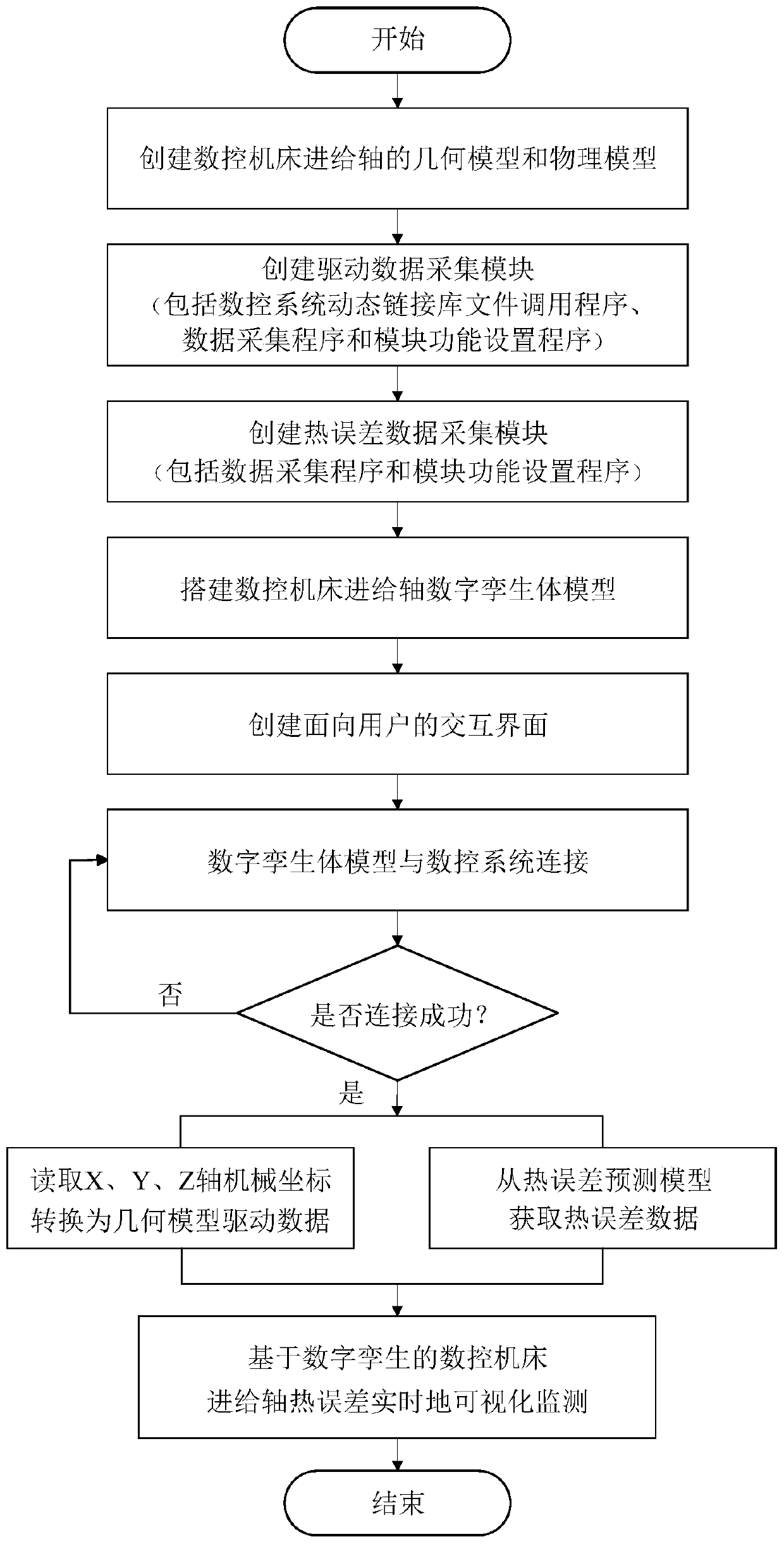
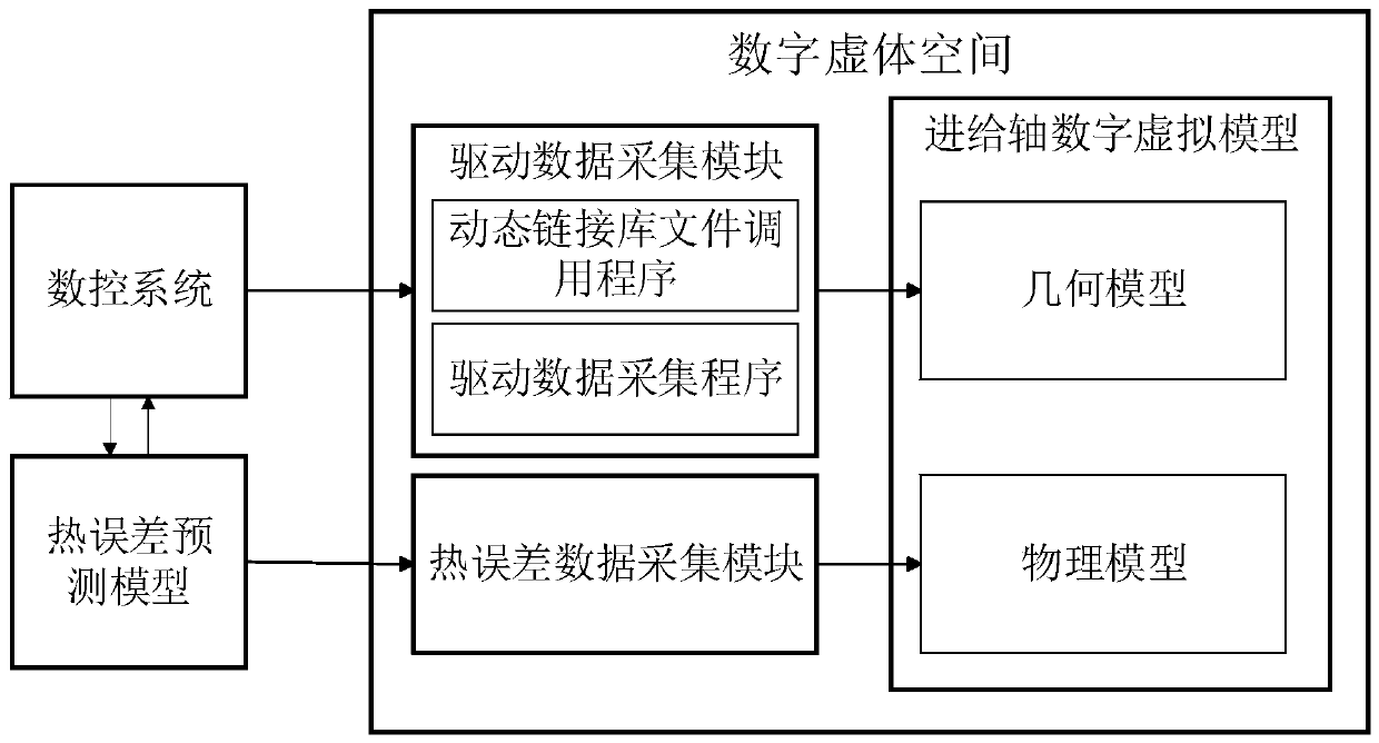
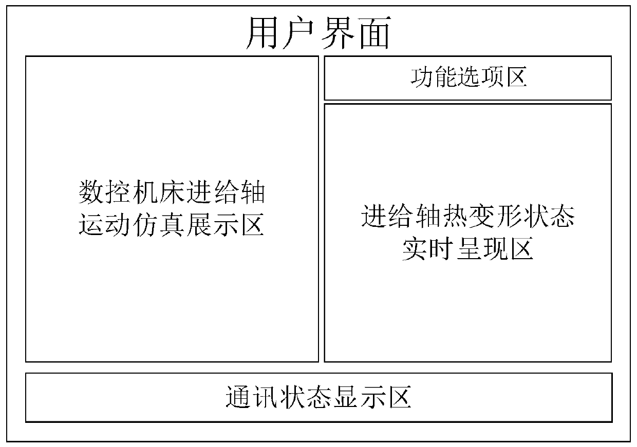
The invention discloses a numerical control machine tool feed shaft thermal error monitoring method based on digital twinning. The method comprises the following steps: creating a virtual digital model of an entity numerical control machine tool feed shaft based on three-dimensional modeling software and MATLAB scripting language; creating a driving data acquisition module based on the MATLAB scripting language and Simulink, and acquiring geometric model driving data from a numerical control system; creating a thermal error data acquisition module based on the Simulink, and obtaining thermal error prediction data; connecting all the modules mentioned above through data input and output interfaces on the basis of Simulink, building a feed shaft digital twinning body model, and achieving three-dimensional real-time presentation of feed shaft thermal errors; and creating a user-oriented interactive interface based on the MATLAB scripting language and the Simulink. According to the method,machine tool feed shaft thermal error monitoring can be displayed from datamation to visualization, and a specific implementation method is provided for application of the digital twinning technologyin the field of numerical control machine tool thermal error monitoring.

Description

technical field [0001] The invention relates to the field of error compensation technology of numerical control machine tools and digital twin technology, and specifically relates to a digital twin-based thermal error monitoring method for feed shafts of numerical control machine tools. Background technique [0002] Thermal error is one of the important factors affecting the accuracy of CNC machine tools. Literature shows that thermal error accounts for about 40% to 70% of the total error of the machine tool, which not only affects the processing accuracy of a single workpiece, but also affects the accuracy consistency of batch processing. The thermal error of CNC machine tools includes two parts: feed axis thermal error and spindle thermal error. At present, the research on the thermal error modeling and compensation of the feed axis of CNC machine tools has become the key research direction of relevant scholars. With the development of a new generation of information tech...

Claims


Application Information

Patent Timeline
Patent Type & Authority Applications(China)
IPC IPC(8): G05B19/4065
CPCG05B19/4065G05B2219/37616
Inventor 刘阔宋磊黄任杰沈明瑞王宏慧王永青
Owner DALIAN UNIV OF TECH
Learn More