Static calibration method for camera external parameters

A technology of external parameters and calibration methods, applied in image data processing, instruments, calculations, etc., can solve problems such as inapplicable calibration methods, lack of reprojection and transformation matrices, etc.

Pending Publication Date: 2020-04-07
BEIJING MOMENTA TECH CO LTD
View PDF13 Cites 3 Cited by
  • Summary
  • Abstract
  • Description
  • Claims
  • Application Information

AI Technical Summary

Problems solved by technology

But the camera and IMU installed on the car cannot shake, so the traditional calibration method is not applicable
[0004] Moreover, in the existing technical solutions, there is still a lack

Method used


Image

  • Static calibration method for camera external parameters
  • Static calibration method for camera external parameters
  • Static calibration method for camera external parameters

Examples


Embodiment 1

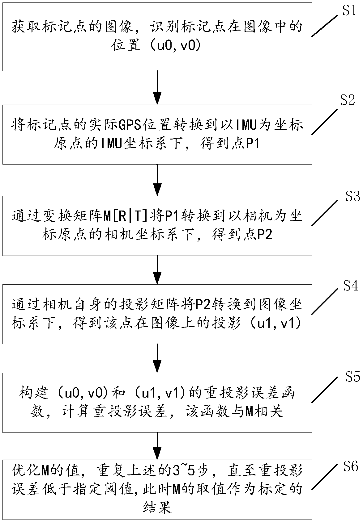
[0042] In this embodiment, through multiple high-resolution cameras or cameras on the top of the vehicle, 360-degree high-definition video or photographing can be realized. When the vehicle is stationary, the calibration method of the external parameters of the camera includes the following steps:

[0043] Step S1: Set one or more marker points, acquire an image including the marker points from the camera on the top of the vehicle, and identify the position (u0, v0) of the marker points in the image. The position of the marker point in the image is the observation value. The marker point here can be a special signboard or a marker pole. Because it occupies a small area and the GPS position is known, the accuracy of the acquired signal is high; the marker point The GPS position is known, which can be measured in advance, obtained directly during calibration, or directly measured using RTK equipment during calibration.

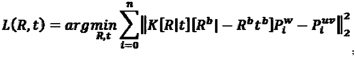
[0044] Since there are 6 external parameters of the camera...

Embodiment 2

[0057] In this embodiment, multiple high-resolution video cameras or cameras can be arranged around the vehicle, as long as 360-degree high-definition video or photographing can be achieved, the method for calibrating the external parameters of the camera includes the following steps:

[0058] Step S1: Set one or more marker points, use cameras or cameras around the vehicle to acquire images including the marker points, and identify the positions (u0, v0) of the marker points in the image. Here, the position coordinates of the marked points in the image can be calculated by the trained neural network, which is trained by a large amount of existing data (that is, the positions of the known marked points in the image have corresponding coordinates).

[0059] Step S2: Convert the actual GPS position of the marked point to the IMU coordinate system with the IMU as the coordinate origin to obtain point P1. Here, the GPS position and the IMU coordinates are both three-dimensional co...


PUM


Abstract

The invention discloses a static calibration method for camera external parameters. The method comprises the following steps: S1, setting a plurality of marking points; S2, converting the actual GPS position of the mark point into an IMU coordinate system taking the IMU as an origin of coordinates to obtain a point P1; S3, converting P1 into a camera coordinate system taking a camera as an originof coordinates by rotating the translation transformation matrix to obtain P2; S4, the P2 is converted into an image coordinate system through an internal reference matrix of the camera device, and projection coordinates of the point on the image are obtained; s5, calculating a re-projection error according to the constructed re-projection error function; and S6, optimizing the rotation translation transformation matrix, and repeating the steps S3 to S5 until the re-projection error is lower than a specified threshold. According to the method, a loss function is constructed through GPS coordinates of mark points and pixel coordinates of the mark points in a camera device to finally obtain an Euclidean transformation relation between the GPS coordinates of the mark points and the pixel coordinates of the mark points, namely a rotation and translation transformation matrix. According to the method, the calibration of the external parameters of the camera can be completed in a static state without reconstructing collection equipment and a vehicle.

Description

technical field [0001] The invention relates to the field of intelligent driving, in particular to a static calibration method for external parameters of a camera. Background technique [0002] At present, the accuracy of autonomous driving maps is measured in the GPS coordinate system, which means that each point on the map needs to be represented by GPS coordinates. In a multi-sensor solution, the camera and GPS may not be installed at the same position in the vehicle at the same time, but may be separated by a distance of 2 to 3 meters. Therefore, it is necessary to calibrate the external parameters of the camera and establish the spatial position relationship between the camera and the GPS module. If the calibration of the camera's external parameters is not carried out, and the map is constructed directly based on the camera image and the position of the car body, an error of two or three meters may eventually occur. [0003] The traditional calibration method needs t...

Claims


Application Information

Patent Timeline
IPC IPC(8): G06T7/80
CPCG06T7/80
Inventor 陈亮李晓东芦超
Owner BEIJING MOMENTA TECH CO LTD
Why Eureka
Try Eureka