Dynamic calibration method for camera external parameters
An external parameter, dynamic calibration technology, applied in image data processing, instruments, calculations, etc., can solve the problem of long time and achieve the effect of short time
- Summary
- Abstract
- Description
- Claims
- Application Information
AI Technical Summary
Problems solved by technology
Method used
Image
Examples
Embodiment 1
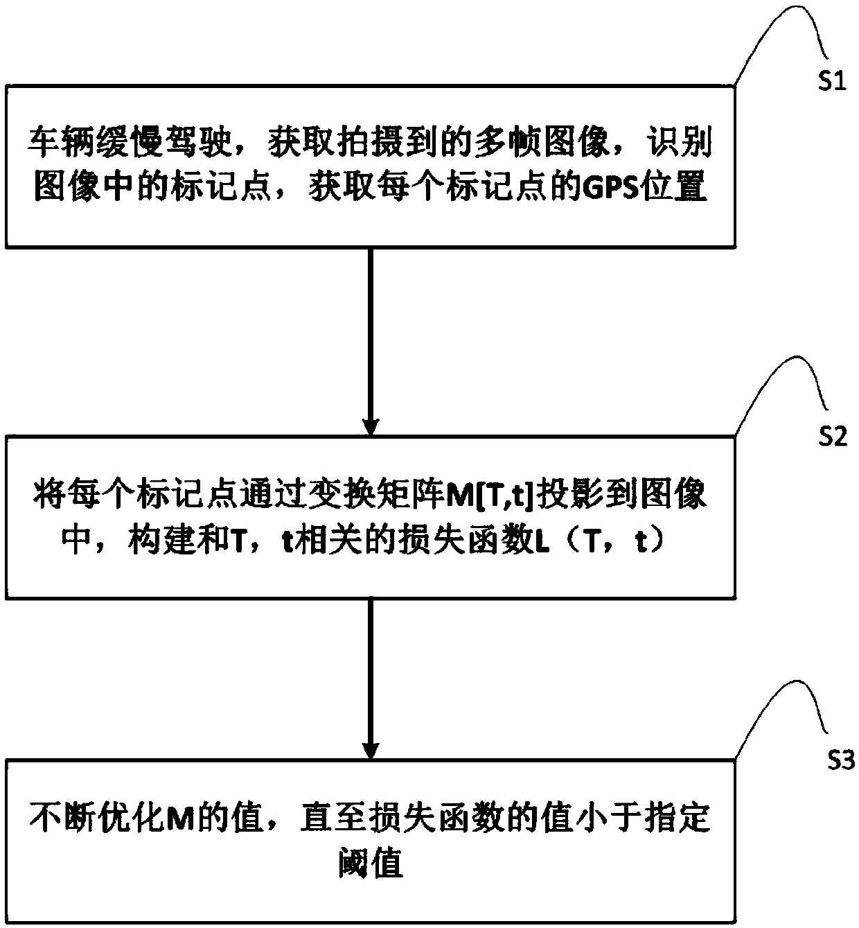
[0048] In this embodiment, through multiple high-resolution cameras on the top of the vehicle, 360-degree high-definition video or photographing can be realized. When the vehicle is stationary, the calibration method of the external parameters of the camera includes the following steps:
[0049] Step S1: set one or more marker points, when the vehicle is driving, preferably at a slow speed, the camera on the top of the vehicle acquires an image including the marker points, identifies the position (u0, v0) of the marker points in the image, and Get the GPS position of each marker. The mark point can be a semantic feature on the road (sign, light pole, etc.), no special settings are required, as long as the GPS position of the point is known, the mark point can be used for calibration.
[0050] Step S2: Project one or more marked points into the image through the transformation matrix M[T|t] to obtain the theoretical projection coordinates (u1, v1) of the point on the image.
...
Embodiment 2
[0063] In this embodiment, multiple high-resolution video cameras or cameras can be arranged around the vehicle, as long as 360-degree high-definition video or photographing can be achieved, the method for calibrating the external parameters of the camera includes the following steps:
[0064] Step S1: The vehicle is moving slowly, cameras or cameras are set up around the vehicle, multiple frames of images are acquired, and the position (u0, v0) of one or more marker points in the image is identified. Here, the position coordinates of the marked points in the image can be calculated by the trained neural network, which is trained by a large amount of existing data (that is, the positions of the known marked points in the image have corresponding coordinates).
[0065] Step S2: Convert the actual GPS position of the marked point to the IMU coordinate system with the IMU as the coordinate origin to obtain point P1. Here, the GPS position and the IMU coordinates are both three-di...
PUM
 Abstract
Description
Claims
Application Information
 - R&D
- Intellectual Property
- Life Sciences
- Materials
- Tech Scout
- Unparalleled Data Quality
- Higher Quality Content
- 60% Fewer Hallucinations
Browse by: Latest US Patents, China's latest patents, Technical Efficacy Thesaurus, Application Domain, Technology Topic, Popular Technical Reports.
© 2025 PatSnap. All rights reserved.Legal|Privacy policy|Modern Slavery Act Transparency Statement|Sitemap|About US| Contact US: help@patsnap.com


