Rotor and motor

A technology of rotor and rotor core, which is applied in the direction of electrical components, electromechanical devices, electric components, etc., and can solve problems such as easy partial demagnetization of the rotor core

Pending Publication Date: 2020-04-07
GUANGDONG WELLING ELECTRIC MACHINE MFG +1
View PDF0 Cites 0 Cited by
  • Summary
  • Abstract
  • Description
  • Claims
  • Application Information

AI Technical Summary

Problems solved by technology

[0004] The purpose of the present invention is to overcome the problem that the rotor core is easy to be partially demagnetized in the prior art, and to provide a rotor that can protect the internal permanent magnet from the magnetic field of the stator and effectively improve the anti-local demagnetization ability of the permanent magnet

Method used


Image

  • Rotor and motor
  • Rotor and motor
  • Rotor and motor

Examples


Embodiment Construction

[0021] Specific embodiments of the present invention will be described in detail below in conjunction with the accompanying drawings. It should be understood that the specific embodiments described here are only used to illustrate and explain the present invention, and are not intended to limit the present invention.

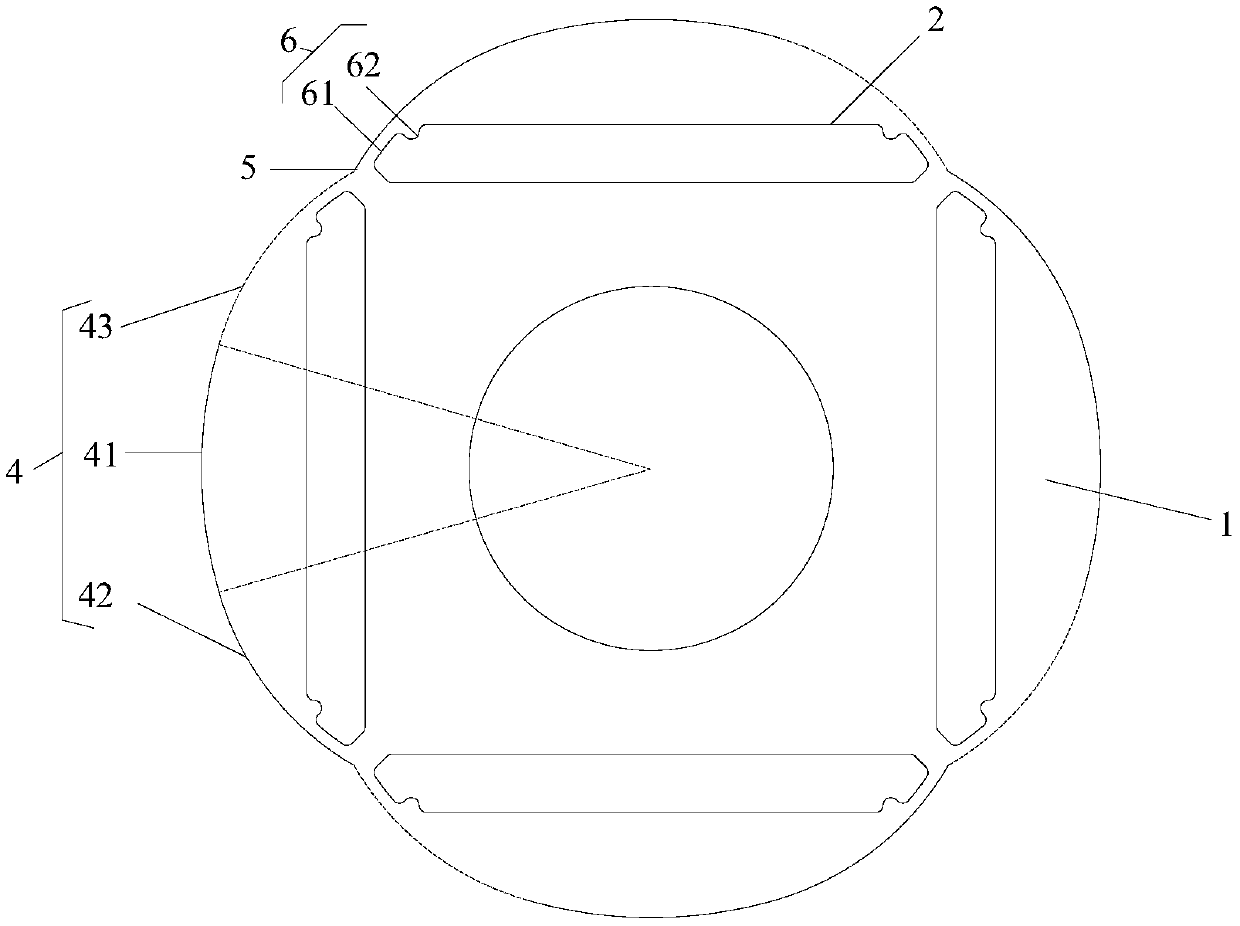
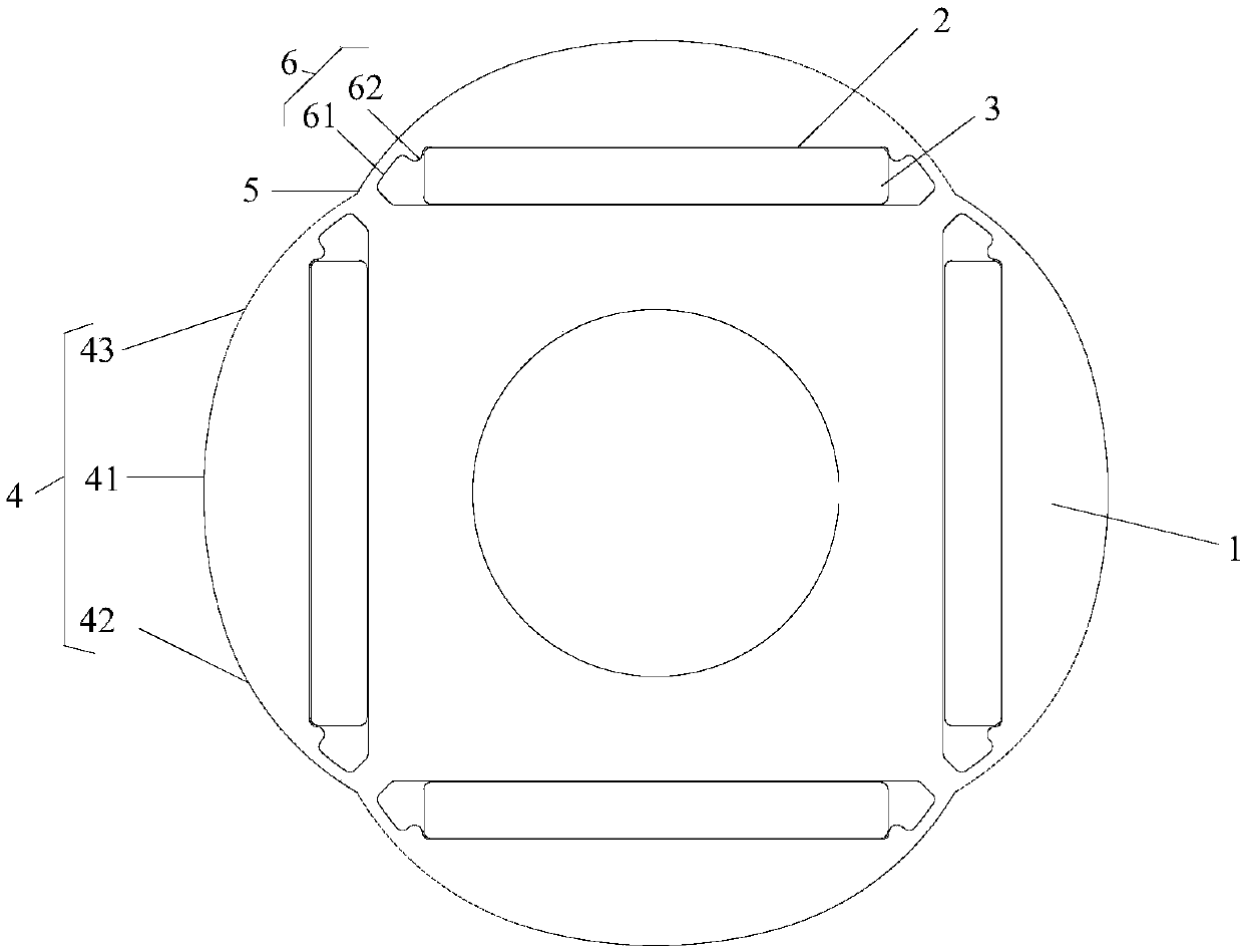
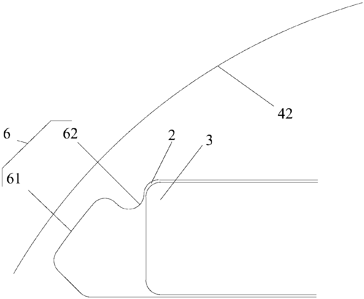
[0022] combine figure 1 , figure 2 , according to one aspect of the present invention, a rotor is provided, including a rotor core 1 and a permanent magnet 3, the rotor core 1 is provided with a plurality of installation slots 2 arranged at intervals along the circumference of the rotor core 1 , the permanent magnets 3 are arranged in the installation grooves 2, each of the installation grooves 2 has a first edge close to the outer edge of the rotor core 1, a second edge toward the center of the rotor core 1 An edge and a transition edge connecting the first edge and the second edge, the transition edge is a multi-segment structure 6, and the part of the mult...


PUM


Abstract

The invention relates to the field of motors, and discloses a rotor and a motor. The rotor comprises a rotor core (1) and permanent magnets (3). The rotor core (1) is provided with a plurality of installation grooves (2) which are arranged at intervals in the circumferential direction of the rotor core (1). The permanent magnets (3) are arranged in the installation grooves (2), wherein each installation groove (2) is provided with a first edge close to the outer edge of the rotor core (1), a second edge facing the center of the rotor core (1) and a transition edge connecting the first edge andthe second edge, each transition edge is of a multi-section structure (6), and the parts, connected with the first edges, of multi-section structures (6) are arranged to protrude towards the inner sides of the installation grooves (2). By arranging the multi-section structures, the distance between the permanent magnets and the outer edge of the rotor core is increased, and the magnetic densityis reduced, so that a magnetic bridge formed between the permanent magnets and the outer edge of the rotor core can protect the permanent magnets from the action of a stator magnetic field, and the local demagnetization resistance of the permanent magnets is effectively improved.

Description

technical field [0001] The invention relates to the field of motors, in particular to a rotor and a motor. Background technique [0002] In the prior art, the design of the built-in permanent magnet motor needs to consider the problem of demagnetization of the permanent magnet, especially the part of the permanent magnet near the edge of the rotor iron core. Since the iron core of this part is thinner, it is more strongly affected by the stator magnetic field, so Very prone to partial demagnetization. [0003] At present, in order to overcome the problem of partial demagnetization of permanent magnets, methods of increasing the thickness of permanent magnets or selecting higher-level permanent magnets are usually used, but these designs will increase the manufacturing cost of the motor. Contents of the invention [0004] The purpose of the present invention is to overcome the problem that the rotor core is easy to be partially demagnetized in the prior art, and to provide...

Claims


Application Information

Patent Timeline
Patent Type & Authority Applications(China)
IPC IPC(8): H02K1/27
CPCH02K1/2766
Inventor 王飞朱嘉东孙权贵
Owner GUANGDONG WELLING ELECTRIC MACHINE MFG
Why Eureka
Try Eureka