Image splicing implementation structure of dental CBCT
A technology of image mosaic and structure connection, which is applied in structure connection, dental radiology diagnosis, medical science, etc. It can solve the problems of large movement distance of the jaw rest positioning mechanism and the detector touching the patient's shoulder, etc., and achieve the effect of improving comfort
- Summary
- Abstract
- Description
- Claims
- Application Information
AI Technical Summary
Problems solved by technology
Method used
Image
Examples
Embodiment 1
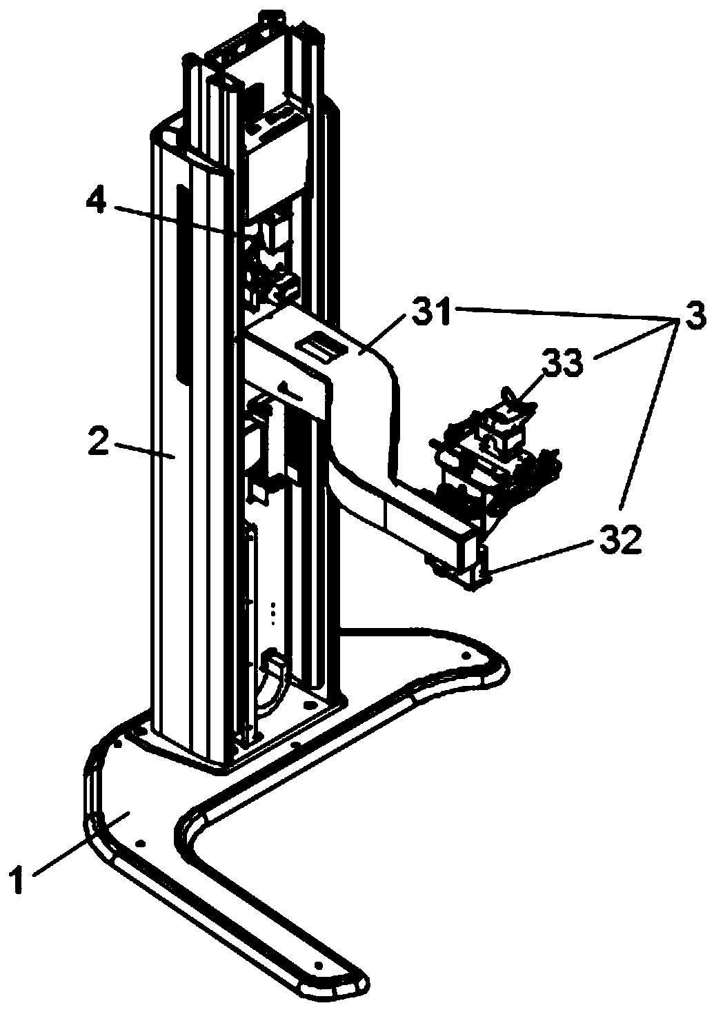
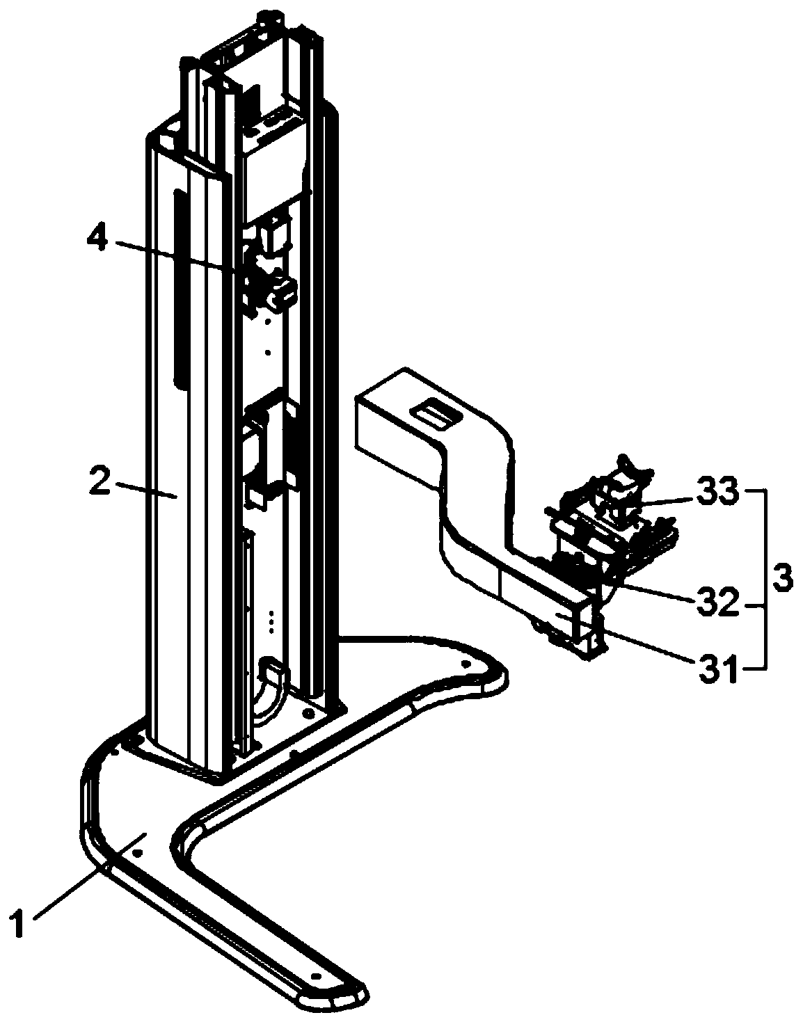
[0041] Such as figure 1 , figure 2 As shown, this embodiment discloses a dental CBCT image mosaic implementation structure, specifically with figure 1 For reference, the orientation includes the base 1, the column lifting mechanism 2, the jaw bracket positioning mechanism 3 and the laser device 4; the bottom of the column lifting mechanism 2 is installed on the base 1 through bolts; the rear end of the jaw bracket positioning mechanism 3 is installed on the column lifting via bolts The middle part of the mechanism 2; the laser device 4 is installed on the upper end of the column lifting mechanism 2 through bolts.
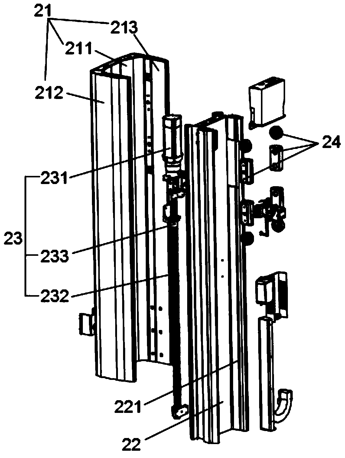
[0042] Such as image 3 As shown, the column lifting mechanism 2 includes a base column 21, a sliding column 22 and a screw lifting assembly 23 guiding mechanism 24; the bottom of the base column 21 is fixed to the middle part of the upper surface of the base 1 by bolts; the sliding column 22 is sleeved on the inside of the base column 21 and Slidingly connected...
Embodiment 2
[0052] Such as Figure 3-5 As shown, the difference between this embodiment and the above-mentioned embodiment is: the column lifting mechanism 2 also includes a guide mechanism 24, and the guide mechanism 24 includes guide rollers 241, fixed plates 242, screws 243, top tight blocks 244, movable guide blocks 245 and fixed Guide block 246; Guide roller 241 is provided with a plurality of, and a plurality of guide rollers 241 are installed in left column 212 and right column 213 inner sides symmetrically by roller axis; 221 rolling fit in its length direction;
[0053] The fixed plate 242 is welded between the two guide rollers 241 inside the left column 212. The central part of the fixed plate 242 is provided with a threaded hole, and the rod portion of the screw 243 is threadedly matched with the threaded hole; Welding and fixing; the middle part of the left side of the movable guide block 245 is provided with a U-shaped chute with a cross-section of "U" shape, the right end ...
Embodiment 3
[0058] Such as Figure 8 As shown, the difference between this embodiment and the above-mentioned embodiment is that: the end of the front side wall of the support plate 321 is equipped with a linear guide rail 3211 through bolts; The middle part is welded and fixed to the front side of the second screw nut 3231; the rear end of the connecting plate 331 is equipped with a slider 3311 through bolts, and the slider 3311 is sleeved on the linear guide rail 3211 and slidably matched with the linear guide rail 3211 in its length direction .
PUM
 Abstract
Description
Claims
Application Information
 - R&D
- Intellectual Property
- Life Sciences
- Materials
- Tech Scout
- Unparalleled Data Quality
- Higher Quality Content
- 60% Fewer Hallucinations
Browse by: Latest US Patents, China's latest patents, Technical Efficacy Thesaurus, Application Domain, Technology Topic, Popular Technical Reports.
© 2025 PatSnap. All rights reserved.Legal|Privacy policy|Modern Slavery Act Transparency Statement|Sitemap|About US| Contact US: help@patsnap.com


