Filtering device for oil exploitation

A filter device and petroleum technology, applied in the direction of filtration separation, filtration circuit, separation method, etc., can solve the problems of oil filtration and treatment, and achieve the effect of facilitating filtration treatment, speeding up the flow rate, and preventing poor fluidity

Inactive Publication Date: 2020-04-10
杭州鹏杰机械制造有限公司
View PDF7 Cites 5 Cited by
  • Summary
  • Abstract
  • Description
  • Claims
  • Application Information

AI Technical Summary

Problems solved by technology

An anti-clogging filter device for oil development in the above-mentioned patent has the following disadvantages: when filtering oil, due to the high concentration of oil, the existing device cannot effectively filter oil

Method used


Image

  • Filtering device for oil exploitation
  • Filtering device for oil exploitation
  • Filtering device for oil exploitation

Examples


Embodiment 1

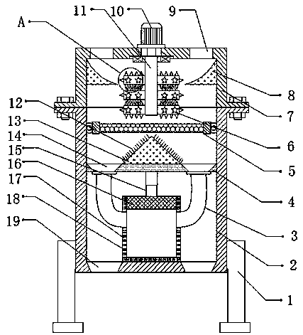
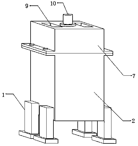
[0029] refer to Figure 1-3 , a filter device for oil development, comprising a filter box 2, the outer walls of both sides of the filter box 2 are connected with two fixed legs 1 by bolts, and both sides of the outer wall of the bottom of the filter box 2 are provided with oil discharge ports 19, the filter box The inner wall of the bottom of the filter box 2 is connected with a filter press cartridge 17 by bolts, and the outer wall of the filter press cartridge 17 is provided with a plurality of filter holes 18, and the inner wall of the filter box 2 near the top is connected with a support plate 4 by bolts, and the support plate 4 The outer wall of the bottom is connected with an electric telescopic rod 15 by bolts, and the outer wall of the bottom of the electric telescopic rod 15 is connected with a piston 16 by bolts. Cover 7, and both sides of case cover 7 top outer wall all have oil inlet 9.

[0030] Wherein, the inner walls on both sides opposite to the box cover 7 a...

Embodiment 2

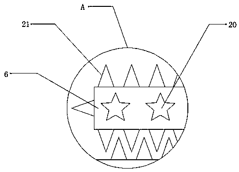
[0039] refer to Figure 4 , a filter device for oil development. Compared with Embodiment 1, the present embodiment has a stop rod 22 connected by bolts between the inner walls on both sides of the tank cover 7, and the cross section of the stop rod 22 is triangular, which can slow down The flow speed of the oil prevents the oil from accumulating and clogging the inside of the device due to the high flow speed of the oil.

[0040]Working principle: when in use, the exploited oil is filled into the inside of the filter box 2 through the oil inlet 9, and the flow speed of the oil can be slowed down by the stop rod 22, preventing the oil from accumulating together due to the fast flow speed of the oil. The inside of the device is blocked, start the motor 10, and the motor 10 will drive the rotating rod 11 to rotate, so that the stirring shaft 6 can stir the oil, and the lumps mixed in the oil can be crushed through the convex teeth 21 to prevent The lumps block the inside of the...


PUM


Abstract

The invention discloses a filtering device for oil exploitation. The device comprises a filter box, two fixing legs are fixed on the outer walls of two sides of the filter box, oil outlets are arranged at two sides of the outer wall of the bottom of the filter box, a filter pressing cylinder is fixed at the inner wall of the bottom of the filter box, a plurality of filter holes are formed in the outer wall of the filter pressing cylinder, a supporting plate is fixed at a position, close to the top, of the inner wall of the filter box, an electric telescopic rod is fixed at the outer wall of the bottom of the supporting plate, a piston is fixed at the outer wall of the bottom of the electric telescopic rod, a filtering net is connected to the inner wall of the filter box through a hinge, and a box cover is fixed to the outer wall of the top of the filter box. The device can prevent the situation that the device cannot effectively filter petroleum with a high concentration, can prevent poor fluidity of the petroleum, caused by excessive petroleum accumulation, and can prevent obstruction in the device due to petroleum accumulation caused by high flow speed of the petroleum.

Description

technical field [0001] The invention relates to the technical field of petroleum exploitation, in particular to a filtering device for petroleum exploitation. Background technique [0002] Petroleum is a fluid mineral buried deep in the ground. At first, people called oily liquid minerals produced in nature petroleum, combustible gas natural gas, and solid combustible fuel minerals as asphalt. The act of digging, extracting, in the process of extracting oil. [0003] After searching, the Chinese patent authorization number is CN208562246U, which discloses a filter device for anti-clogging oil development, including a lower casing, the top of the lower casing is provided with an upper casing, and the middle of the bottom of the lower casing is A first rotating motor is fixedly connected at the point, and a first rotating shaft is fixedly connected to the output shaft of the first rotating motor, and the top of the first rotating shaft penetrates the lower casing and extends ...

Claims


Application Information

Patent Timeline
Patent Type & Authority Applications(China)
IPC IPC(8): B01D36/02B02C18/10B02C18/18
CPCB01D36/02B02C18/10B02C18/18
Inventor 何燕
Owner 杭州鹏杰机械制造有限公司
Why Eureka
Try Eureka