Bending device for hardware machining

A bending device and hardware technology, applied in metal processing equipment, feeding devices, positioning devices, etc., can solve the problems of affecting the bending process, inconvenient metal tube bending, trouble, etc., and achieve the effect of reducing friction

Inactive Publication Date: 2020-04-10
谢建金
View PDF6 Cites 0 Cited by
  • Summary
  • Abstract
  • Description
  • Claims
  • Application Information

AI Technical Summary

Problems solved by technology

[0004] When the current bending device for metal processing is bending the pipe, because the parts for bending processing have no supporting parts, and the length of the pressure roller and the idler roller is also long, it is difficult to bend a single metal pipe. At the same time, the metal tube is easy to slide on the pressure roller and the idler, which affects the process of bending the pipe. However, shortening the pressure roller and the idler is not convenient for bending multiple metal tubes, and it is more troublesome to use.

Method used


Image

  • Bending device for hardware machining
  • Bending device for hardware machining
  • Bending device for hardware machining

Examples


Embodiment 1

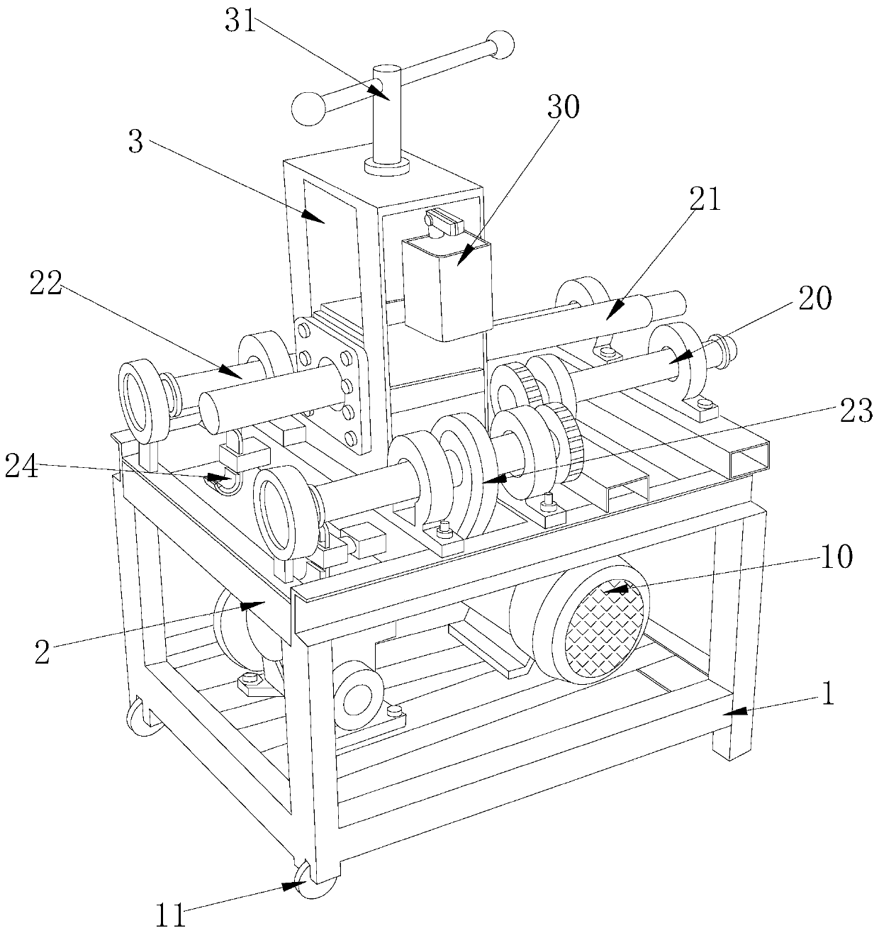
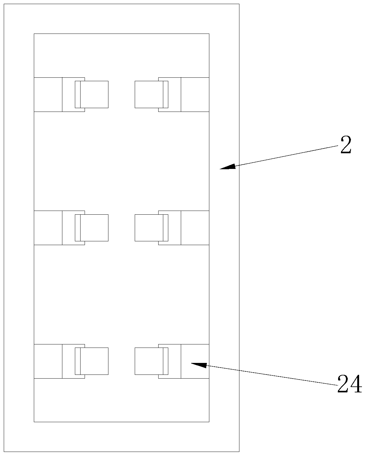
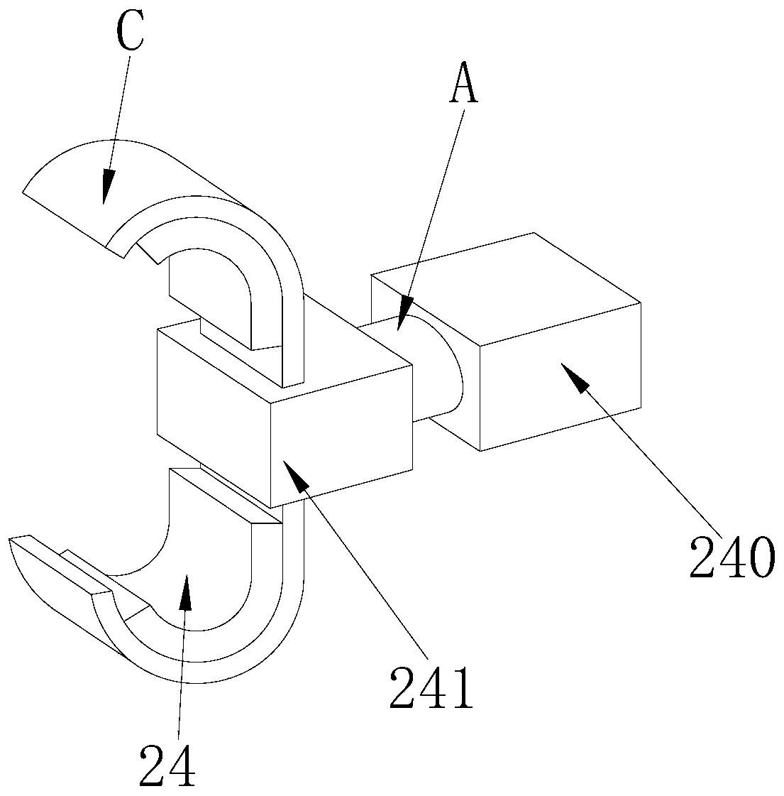
[0029] Embodiment 1: When in use, the clamper 241 is driven by the hydraulic pusher 240 to adjust the distance, and at the same time, it can clamp 1-3 metal tubes, and then squeeze the metal tubes into the clamper 241 to make the clamping The clamp 241 can be opened to reach the maximum diameter of the metal tube, so as to clamp the metal tube; the push rod A on the hydraulic pusher 240 is pushed by the auxiliary push of the sealing ring B to push the clamp 241 to move until it stretches to Put the metal tube into the clamp 241; through the metal tube squeeze between the splints C, so that the splint C is opened, and under the control of the spring D, the splint C is opened to the diameter value suitable for the hardware tube, and at the same time through the spring D Drive splint C to clamp.

Embodiment 2

[0030] Embodiment 2: After the clamping work of the metal tube is completed, the splint C is fixed on the clamp 241 through the clamp C1, and at the same time, with the assistance of the cotton pad C2, the metal tube can be bent during the bending process. Sliding in the splint C can ensure the longitudinal sliding of the metal tube while realizing the horizontal clamping of the metal tube, so as to facilitate the bending of the metal tube by assisting the left idler 20, the pressure roller 21 and the right idler 22 fold work.

[0031] The technical progress that the present invention obtains relative to the prior art is:

[0032] 1. Push the clamp to clamp the metal tube through the hydraulic pusher, and at the same time make the limit clamp suitable for one or more metal tubes for simultaneous bending processing. By squeezing the metal tube into the clamp, Then, it is clamped by the spring and the splint, so as to realize the horizontal fixation of the metal tube;

[0033]...


PUM


Abstract

The invention discloses a bending device for hardware machining. The bending device structurally comprises an underframe, a supporting frame and a bending controller. The underframe is provided with amotor and walking wheels. The supporting frame is provided with a left carrier roller, a pressing roller, a right carrier roller, a chain and limiting clamping devices. The bending controller is provided with a controller and an adjusting handle. The bending device for hardware machining has the beneficial effects that hydraulic pushers push clamping devices to clamp hardware pipes, at the same time, the limiting clamping devices can be suitable for conducting bending machining on one or more hardware pipes at the same time, and the hardware pipes are extruded into the clamping devices and then clamped through springs and clamping plates, so that transverse fixing of the hardware pipes is achieved; cotton pads on the clamping plates are in contact with the hardware pipes, so that the friction between the hardware pipes and the clamping plates is reduced; and moreover, under assistance of the round hook-shaped structures of the clamping plates, the hardware pipes can be driven to longitudinally slide in the bending process, so that the situation that in the bending process of the hardware pipe, the left carrier roller, the pressing roller and the right carrier roller run around, and the bending quality is affected is avoided.

Description

technical field [0001] The invention relates to the field of hardware processing, in particular to a bending device for hardware processing. Background technique [0002] At present, the level of domestic production technology is uneven. During the transition period of China's hardware from low-end to high-end products, raw materials and production technology are very important. Hardware production and processing have also changed from the original manual to hydraulic automation. With the hardware processing With the advancement of technology, the requirements for the use of bending devices for metal processing have also increased. [0003] Aiming at the current bending device for metal processing, a relative plan has been formulated for the following problems: [0004] When the current bending device for metal processing is bending the pipe, because the parts for bending processing have no supporting parts, and the length of the pressure roller and the idler roller is also...

Claims


Application Information

Patent Timeline
Patent Type & Authority Applications(China)
IPC IPC(8): B21D7/06B21D43/00
CPCB21D7/06B21D43/003
Inventor 谢建金
Owner 谢建金
Why Eureka
Try Eureka