Clamping device for PCB production

A clamping device and PCB board technology, which is applied in the assembly of printed circuits with electrical components, the positioning of circuit board tools, electrical components, etc., can solve the problems of insufficient stability, inconvenient operation of the clamping device, and cumbersome operation methods.

Inactive Publication Date: 2020-04-10
河南聚桓电子科技有限公司
View PDF1 Cites 1 Cited by
  • Summary
  • Abstract
  • Description
  • Claims
  • Application Information

AI Technical Summary

Problems solved by technology

[0003] In the production of PCB boards, electronic components need to be installed on the PCB board, but some PCB boards need to be welded on both sides of the electronic components. The existing clamping device is inconvenient to operate and disassemble, which is not conducive to the replacement of the clip. Processing of PCB boards meeting different specifications
[0004] In the Chinese utility model patent document with the publication number CN208113094U, a clamping device for PCB board production is disclosed. When the PCB board needs to be clamped, the PCB board is placed in the first clip and the second clip Then turn the threaded rod, the threaded rod and the support seat will undergo a threaded movement, resulting in relative displacement, the threaded rod will move to the left, push the support frame to move to the left, the sliding seat will move to the left along the chute, and the second clip will move to the left, Clamp the PCB board to complete the clamping, which is convenient and quick; after the electronic components on one side of the PCB board are soldered, when the PCB board needs to be turned over, the positioning pin is moved downward, the spring is compressed, the positioning pin leaves the first positioning slot, and then the handle is turned , the positioning ring rotates, the square rod rotates, the cylinder rotates, the first clip rotates, the PCB board flips, the second clip rotates, the rotating shaft rotates, the annular groove and the limit rod slide relative to each other, and after the PCB board is flipped, release the positioning Pin, under the compression force of the spring, the positioning pin snaps into the second positioning groove, the positioning ring realizes positioning, and the PCB board realizes positioning, which is convenient for the staff to install electronic components on the other side of the PCB board; when it is necessary to disassemble the first When the clip and the second clip are used, remove the PCB board, then move the first clip to the right, the cylinder moves to the right, the square rod leaves the magnet, the first clip can be removed, and then the limit rod is removed from the support Take it out from the block, the limit rod leaves the annular groove, and the second clip can be moved to the left, and the rotating shaft leaves the second through hole, and the disassembly can be completed. Although this device can realize the clamping of the PCB board, the operation method is cumbersome. And because the PCB board is relatively thin, the stability is not high enough during the clamping process

Method used


Image

  • Clamping device for PCB production
  • Clamping device for PCB production
  • Clamping device for PCB production

Examples


Embodiment 1

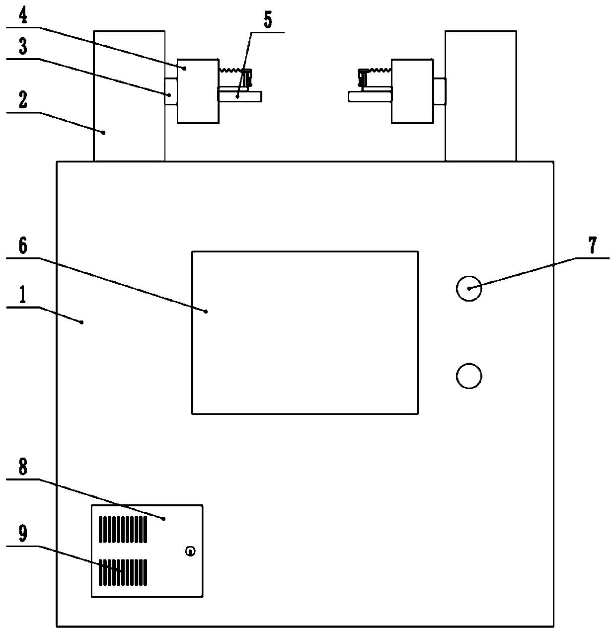
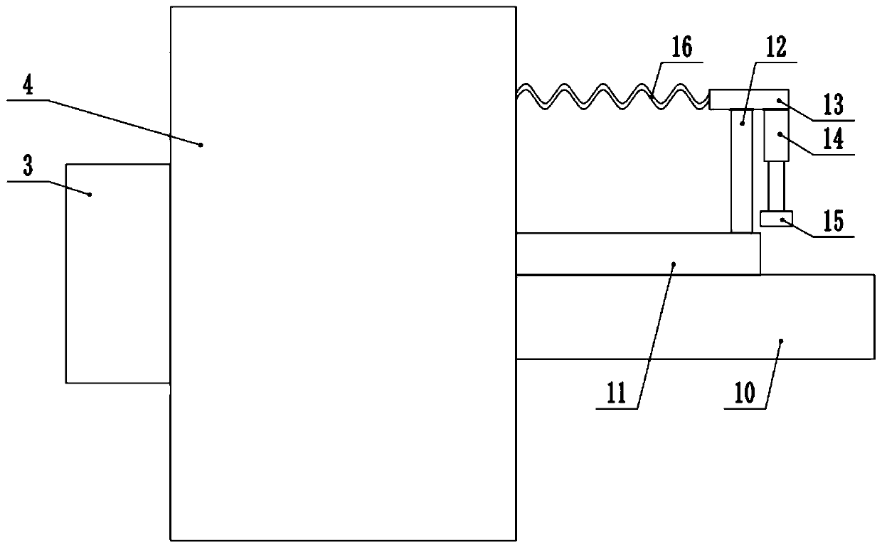
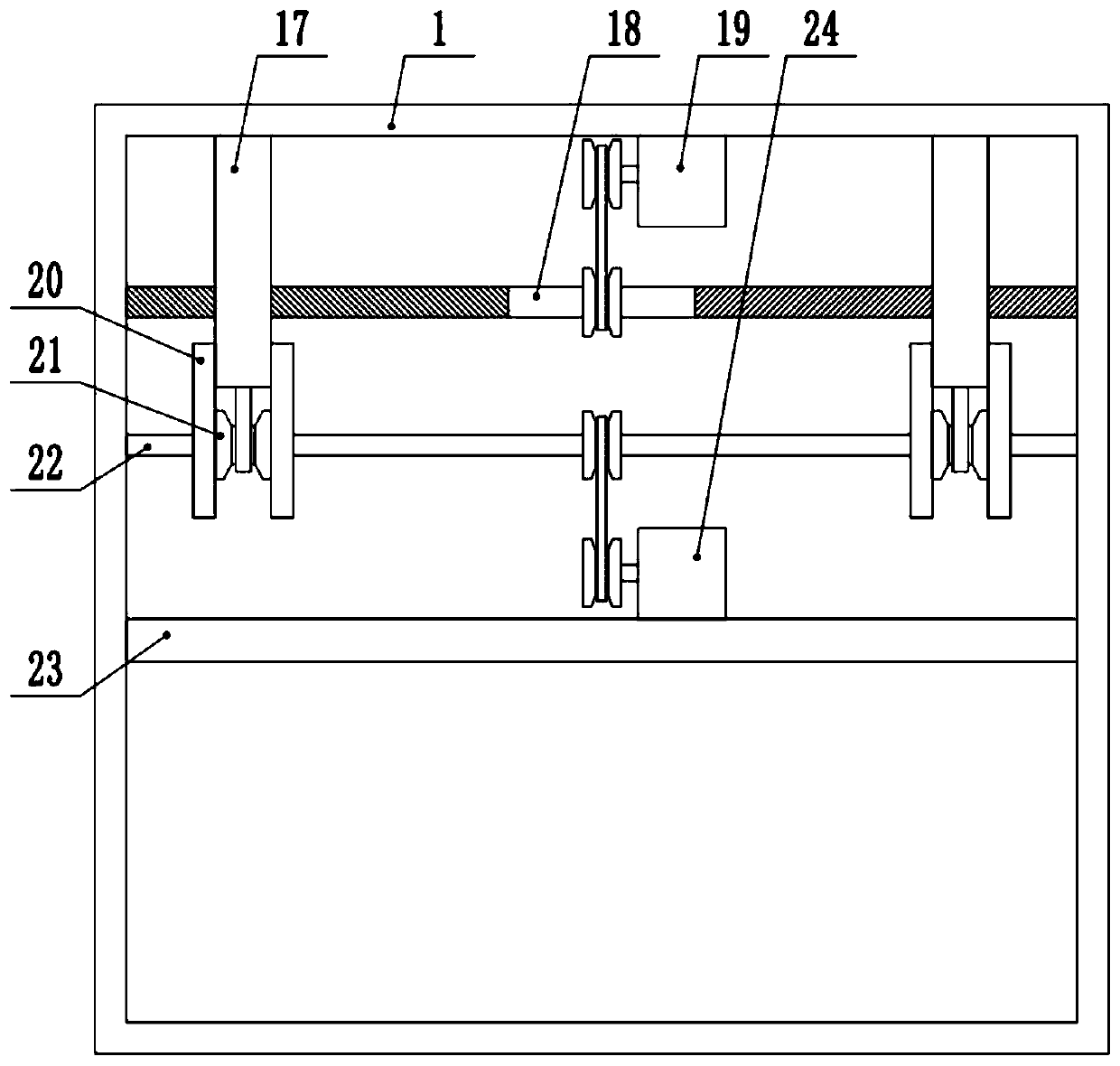
[0027] see Figure 1-4 , a clamping device for PCB board production, comprising an equipment box 1, the top surface of the equipment box 1 is slidably provided with two top seats 2, and the adjacent sides of the two top seats 2 are rotatably connected to a rotating column 3, One end of the rotating column 3 away from the top base 2 is fixedly connected to the rotating base 4, and the end of the rotating base 4 away from the rotating column 3 is provided with a clamping mechanism 5, and the device box 1 is provided with a drive for driving the clamping mechanism 5 to move and rotate. mechanism, the drive mechanism includes a first rotating rod 18 and a second rotating rod 22 horizontally arranged in the equipment box 1, the second rotating rod 22 is sheathed with a first transmission wheel 21, and one end of the rotating column 3 is located on the top seat 2 and coaxially fixedly connected to the second transmission wheel, the first transmission wheel 21 is connected to the sec...

Embodiment 2

[0031] see Figure 1-4 , a clamping device for PCB board production, comprising an equipment box 1, the top surface of the equipment box 1 is slidably provided with two top seats 2, and the adjacent sides of the two top seats 2 are rotatably connected to a rotating column 3, One end of the rotating column 3 away from the top base 2 is fixedly connected to the rotating base 4, and the end of the rotating base 4 away from the rotating column 3 is provided with a clamping mechanism 5, and the device box 1 is provided with a drive for driving the clamping mechanism 5 to move and rotate. mechanism, the drive mechanism includes a first rotating rod 18 and a second rotating rod 22 horizontally arranged in the equipment box 1, the second rotating rod 22 is sheathed with a first transmission wheel 21, and one end of the rotating column 3 is located on the top seat 2 and coaxially fixedly connected to the second transmission wheel, the first transmission wheel 21 is connected to the sec...


PUM


Abstract

The invention discloses a clamping device for PCB production, and relates to the technical field of PCB auxiliary processing. The device comprises a device box. Two top seats are arranged on the top surface of the equipment box in a sliding manner. The adjacent sides of the two top seats are rotationally connected with rotating columns. The end, away from the top base, of the rotating column is fixedly connected with rotating bases. A clamping mechanism is arranged at the end, away from the rotating column, of the rotating base. A driving mechanism for driving the clamping mechanism to move and rotate is arranged in the device box. The driving mechanism comprises a first rotating rod and a second rotating rod which are horizontally arranged in the device box. The second rotating rod is sleeved with a first transmission wheel. According to the invention, through arranging the clamping mechanism and the driving mechanism, transverse clamping of the PCB can be achieved, vertical pressingof the PCB can be synchronously achieved, and therefore the PCB can be comprehensively fixed, the clamped and fixed PCB can be rotated according to needs, machining operation in multiple directions can be adapted, and subsequent machining work can be conveniently carried out.

Description

technical field [0001] The invention relates to the technical field of auxiliary processing of PCB boards, in particular to a clamping device for PCB board production. Background technique [0002] PCB board, also known as integrated circuit board, is based on an insulating board, cut to a certain size, with at least one conductive pattern attached to it, and holes (such as component holes, fastening holes, metallized holes, etc.) To replace the chassis of the previous installation of electronic components, and realize the interconnection between electronic components. [0003] In the production of PCB boards, electronic components need to be installed on the PCB board, but some PCB boards need to be welded on both sides of the electronic components. The existing clamping device is inconvenient to operate and disassemble, which is not conducive to the replacement of the clip. Processing of PCB boards meeting different specifications. [0004] In the Chinese utility model p...

Claims


Application Information

Patent Timeline
Patent Type & Authority Applications(China)
IPC IPC(8): H05K3/00H05K3/34
CPCH05K3/0008H05K3/34
Inventor 上官芳刘惠珂
Owner 河南聚桓电子科技有限公司
Why Eureka
Try Eureka