Synchronous wrench for bolts arranged in annular array

A ring array and bolt technology, which is applied in the field of synchronous wrench for setting bolts in ring array, can solve problems such as large limitations, low thread life, and fastening angle deviation of connecting parts, so as to improve efficiency, improve protection ability, and reduce safety. hidden effect

Inactive Publication Date: 2020-04-10
薛春红
View PDF7 Cites 1 Cited by
  • Summary
  • Abstract
  • Description
  • Claims
  • Application Information

AI Technical Summary

Problems solved by technology

[0002] At present, the installation between the sealing cover and the cylinder body of large-scale equipment is fastened by bolts, and the common fastening method is to install bolts one by one, which will lead to the connection caused by the force of a single bolt. The deviation of the fastening angle of the components and the occurrence of the phenomenon of lower service life caused by thread damage have relatively large limitations.

Method used


Image

  • Synchronous wrench for bolts arranged in annular array
  • Synchronous wrench for bolts arranged in annular array
  • Synchronous wrench for bolts arranged in annular array

Examples


Embodiment Construction

[0020] The following will clearly and completely describe the technical solutions in the embodiments of the present invention with reference to the accompanying drawings in the embodiments of the present invention. Obviously, the described embodiments are only some, not all, embodiments of the present invention. Based on the embodiments of the present invention, all other embodiments obtained by persons of ordinary skill in the art without making creative efforts belong to the protection scope of the present invention.

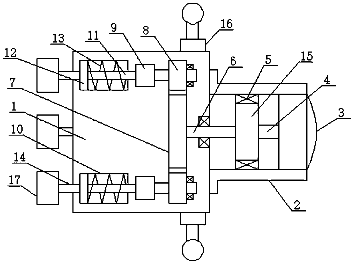
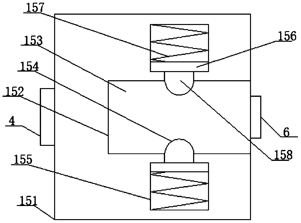
[0021] see figure 1 , an embodiment provided by the present invention: includes a main body housing 1, a drive motor installation shell 2 is installed on one end of the main body shell 1 through bolts, and a drive motor 3 is installed at one end of the drive motor installation shell 2, An annular array helical spring type maximum rotational strength control mechanism 15 is installed at the end of the motor main shaft 4 in the drive motor 4, and the side surfac...


PUM


Abstract

The invention discloses a synchronous wrench for bolts arranged in an annular array mode. The synchronous wrench comprises a main body shell. According to the invention, a plurality of bolts can be rotated to bolt holes in which the bolts need to be mounted at the same time under the effect of synchronous rotation, therefore, the phenomena that due to the fact that a single bolt is stressed, the fastening angle of a connecting part deviates and the threads are damaged, the service life is short can be effectively prevented. The protection capability on the bolt structure is improved; potentialsafety hazard degree reduction, an annular array type longitudinal and transverse staggered rod body linkage mechanism is arranged; longitudinal and transverse cross arrangement is utilized; therefore, the transmission effect of rotation is realized; meanwhile, due to point contact and small friction force, longitudinal movement is not greatly affected, the efficiency is improved, and potential safety hazards in use are reduced; and in addition, the wrench is provided with an annular array spiral spring type maximum rotating strength control mechanism, and the phenomenon that a threaded structure is damaged due to the fact that the rotating strength is too large is avoided.

Description

technical field [0001] The invention relates to the technical field of drive devices, in particular to a synchronous wrench for setting bolts in an annular array. Background technique [0002] At present, the installation between the sealing cover and the cylinder body of large-scale equipment is fastened by bolts, and the common fastening method is to install bolts one by one, which will lead to the connection caused by the force of a single bolt. The deviation of the fastening angle of the parts and the occurrence of the phenomenon of lower life caused by the damage of the thread are more limited. Contents of the invention [0003] The object of the present invention is to provide a synchronous wrench for setting bolts in an annular array, so as to solve the problems raised in the above-mentioned background technology. [0004] In order to achieve the above object, the present invention provides the following technical solutions: a synchronous wrench for setting bolts i...

Claims


Application Information

Patent Timeline
IPC IPC(8): B25B13/48B25B23/00
CPCB25B13/48B25B23/00
Inventor 薛春红
Owner 薛春红
Why Eureka
Try Eureka