Vehicle headlamp control method, vehicle headlamp control system and vehicle

A control method and control system technology, applied in the direction of headlights, vehicle components, optical signals, etc., can solve problems such as intelligent headlight lighting, hidden safety hazards, and impact on driving safety, so as to achieve the effect of improving safety

Inactive Publication Date: 2020-04-10
BEIJING HAINACHUAN AUTOMOTIVE PARTS
5 Cites 5 Cited by

AI-Extracted Technical Summary

Problems solved by technology
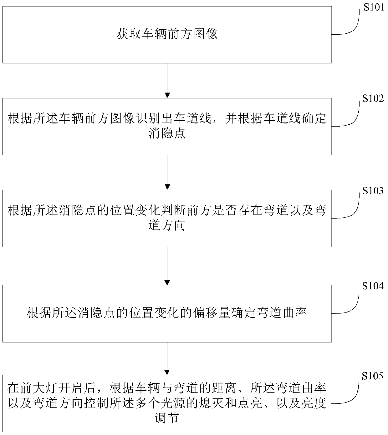
[0003] When there is a curve in the road ahead, the smart headlights cannot illuminate the curve. Therefore...

Abstract

The invention provides a vehicle headlamp control method, a vehicle headlamp control system and a vehicle. The method comprises the following steps: obtaining a vehicle front image; recognizing a laneline according to the vehicle front image, and determining a vanishing point according to the lane line; judging whether a curve exists in front or not and judging the direction of the curve according to the position change of the vanishing point; determining a curvature of the curve according to the offset of the position change of the vanishing point; and controlling the light sources to be turned off and turned on and adjusting the brightness according to a distance between the vehicle and the curve, the curvature of the curve and the direction of the curve after the headlamp is turned on.The vehicle headlamp control method can judge whether the curve exists in front of the vehicle or not and the curvature and the curve direction of the curve in advance, so that the headlamp can be controlled in advance, and the curve area is illuminated, thereby the driving safety is improved.

Application Domain

Vehicle headlampsOptical signalling

Technology Topic

Driving safetyHeadlamp +5

Image

  • Vehicle headlamp control method, vehicle headlamp control system and vehicle
  • Vehicle headlamp control method, vehicle headlamp control system and vehicle
  • Vehicle headlamp control method, vehicle headlamp control system and vehicle

Examples

  • Experimental program(1)

Example Embodiment

[0028] The embodiments of the present application are described in detail below. Examples of the embodiments are shown in the accompanying drawings, wherein the same or similar reference numerals represent the same or similar elements or elements with the same or similar functions. The embodiments described below with reference to the drawings are exemplary, and are only used to explain the present application, and cannot be understood as a limitation to the present application.
[0029] In the description of this application, it should be understood that the terms "center", "vertical", "horizontal", "upper", "lower", "front", "rear", "left", "right", " The orientation or positional relationship indicated by "vertical", "horizontal", "top", "bottom", "inner", "outer" etc. is based on the orientation or positional relationship shown in the drawings, and is only for the convenience of describing the application and The description is simplified, rather than indicating or implying that the pointed device or element must have a specific orientation, be constructed and operated in a specific orientation, and therefore cannot be understood as a limitation of the present application. In addition, the terms "first" and "second" are only used for descriptive purposes, and cannot be understood as indicating or implying relative importance.
[0030] The following describes the vehicle headlight control method, system and vehicle according to the embodiments of the present application in conjunction with the accompanying drawings.
[0031] Among them, the headlight includes a car light array composed of multiple light sources. The light source is, for example, an LED light source. Each LED light source can be independently switched on and off, or multiple light sources can be divided into multiple groups, each group can perform independently Open and close control. In addition, the headlights are usually the headlights of the vehicle. Each light source illuminates a certain angular range, so that the irradiated angles of multiple light sources can constitute the entire irradiated range of the headlight.
[0032] figure 1 It is a flowchart of a method for controlling the headlight of a vehicle according to an embodiment of the present application. Such as figure 1 As shown, the headlight control method according to an embodiment of the present application includes the following steps:
[0033] S101: Acquire an image in front of the vehicle.
[0034] For example: Obtain the image in front of the vehicle through the camera.
[0035] S102: Identify the lane line according to the image in front of the vehicle, and determine the blanking point according to the lane line.
[0036] In an embodiment of the present application, identifying lane lines according to the image in front of the vehicle, and determining a blanking point according to the lane lines, includes: obtaining a grayscale image according to the image in front of the vehicle; identifying according to the grayscale image The lane line; the blanking point is determined according to the intersection of the lane line.
[0037] Combine figure 2 As shown, the collected image in front of the vehicle is grayscaled to obtain a grayscale image. The grayscale image is recognized by jumps line by line, so that the lane line features are extracted, and then the lane lines are identified through clustering. After that, the lane lines can be denoised according to the Kalman filter, and the obtained lane lines can be used for two The equation is expressed. Such as figure 2 The three lane lines identified in, namely: L1, L2 and L3.
[0038] After the lane lines are identified, the parallel lane lines on the road are combined at a point on the image, which is the hidden point in the perspective relationship. According to the identified intersecting lines, the point with the largest number of intersecting lines is selected as the blanking point, such as figure 2 The middle O point is the blanking point.
[0039] S103: Determine whether there is a curve ahead and the direction of the curve according to the position change of the blanking point. For example: obtain the offset of the position change of the blanking point; determine whether the offset is greater than the preset offset of the position change of the blanking point for straight driving; if so, determine that there is a curve ahead The direction of the curve is determined according to the offset direction of the position change of the blanking point.
[0040] In a specific example, a rectangle can be selected, and the length and width of the rectangle can be adjusted as needed. Five pixels are used to represent a blanking point. In this way, as the identified lane line changes, the blanking point also changes; as the steering wheel angle of the vehicle changes, the blanking point also changes.
[0041] When the steering wheel angle is within +/-5 degrees and the rate of change of the steering wheel angle is less than or equal to 5 degrees/second, it can be considered that the change of the steering angle does not affect the selection of the blanking point.
[0042] In an embodiment of the present application, judging whether there is a curve in the front lane and determining the direction of the curve according to the position change of the blanking point includes: recording the position of the blanking point in the current frame, that is, the coordinates of the pixels. Considering that the vehicle will change the running direction of the vehicle according to the left and right rotation of the steering wheel, the experimental method can be formulated in advance, for example:
[0043] On a long straight track, record the change range of the blanking point of the steering wheel to the left or right when the rate of change of the steering wheel angle is less than or equal to 5 degrees/sec. During this period, in the horizontal direction, the blanking point will move to the left or right, and the pixel position information after the movement is recorded, SHO L And SHO R.
[0044] On long straight road + curve (curve radius R=200m, 300m, 400m, 500m, 600m, 700m, 800m, 900m and 1000m), record the steering wheel to the left or right at Lower than the change range of the blanking point when the steering wheel angle change rate is less than or equal to 5 degrees/sec. During this period, in the horizontal direction, the blanking point will move to the left or right, and the pixel position information after the movement is recorded, MHO L R and MHO R R.
[0045] S104: Determine the curvature of the curve according to the offset of the position change of the blanking point.
[0046] In a specific example, according to the offset of the position change of the blanking point, the curve radius can be found from the relationship curve corresponding to the preset offset of the position change of the blanking point and the curve radius, and according to The radius of the curve obtains the curvature of the curve.
[0047] According to the maximum horizontal offset MHO of the blanking point under different curve radii L R and MHO R R, when R continuously changes from 200 meters to 1000 meters, the obtained MHO L R and MHO R R performs linear interpolation to obtain a continuous curve, such as image 3 As shown, the relationship curve corresponding to the offset of the preset blanking point position change and the curve radius is obtained.
[0048] The actual blanking point moves to the left, and its lateral value is greater than SHO L And SHO R When the blanking point moves to the left, it can be judged that there is a curve ahead, and the direction is to the left; the blanking point moves to the right, it can be judged that there is a curve ahead, and the direction is to the right; changes according to the preset blanking point position The curve of the corresponding relationship between the offset and the radius of the curve, the radius of the curve R can be determined, and the curvature F=1/R can be calculated.
[0049] S105: After the headlights are turned on, control the extinguishing and lighting of the multiple light sources and brightness adjustment according to the distance between the vehicle and the curve, the curvature of the curve, and the direction of the curve. For example, according to the distance between the vehicle and the curve, the curvature of the curve, and the direction of the curve, the light source corresponding to the curve area is obtained, and the brightness of the light source corresponding to the curve area is increased.
[0050] In specific applications, the field of view of the vehicle lights can be partitioned according to the number and layout of the LED lights. According to different needs, there can be N multiple LED light sources and light source distribution methods. Examples are as follows, such as Figure 4 Shown: a 4 times 12 LED matrix, a total of 48 LED light sources, different LEDs can be combined to be responsible for a certain light zone. Can form 36 light zones, such as Figure 5 Shown. Obtain that there is a curve D meters ahead, and the curvature is F, direction: left or right.
[0051] Further, according to the predicted curvature value and direction and the distance from the curve to the vehicle, as shown in Table 1, perform the following actions:
[0052] Table 1
[0053]
[0054]
[0055] Further, in order to save energy, all LEDs work at 80% brightness.
[0056] According to the vehicle headlight control method of the embodiment of the present application, it is possible to prejudge whether there is a curve ahead, the curvature of the curve and the direction of the curve, so that the headlights can be controlled in advance to illuminate the curve area , Thereby enhancing the safety of driving.
[0057] Image 6 It is a structural block diagram of a vehicle headlight control system according to an embodiment of the present application. Such as Figure 5 As shown, a vehicle headlight control system 600 according to an embodiment of the present application includes: an acquisition module 610, an identification module 620, and a control module 630.
[0058] Wherein, the acquisition module 610 is used to acquire the image of the front of the vehicle; the recognition module 620 is used to identify the lane line according to the image of the front of the vehicle, and determine the blanking point according to the lane line, and determine whether the front is ahead according to the position change of the blanking point There are curves and the direction of the curve, and the curvature of the curve is determined according to the offset of the position change of the blanking point; the control module 630 is used for after the headlights are turned on, according to the distance between the vehicle and the curve, the curve The curvature of the road and the direction of the curve control the extinguishing and lighting of the multiple light sources and the brightness adjustment.
[0059] In an embodiment of the present application, the recognition module 620 is configured to obtain a grayscale image according to the image in front of the vehicle, and recognize the lane line according to the grayscale image, and determine according to the intersection of the lane line The blanking point.
[0060] In an embodiment of the present application, the identification module 620 is configured to obtain the offset of the position change of the blanking point, and determine whether the offset is greater than the preset position change of the blanking point for straight driving If it is, it is determined that there is a curve ahead, and the curve direction is determined according to the offset direction of the position change of the blanking point.
[0061] In an embodiment of the present application, the identification module 620 is configured to change the offset from the preset blanking point position and the curve radius according to the offset of the position change of the blanking point. Find the radius of the curve in the relationship curve, and obtain the curvature of the curve according to the radius of the curve.
[0062] According to the vehicle headlight control system of the embodiment of the present application, it is possible to pre-determine whether there is a curve ahead and the curvature and direction of the curve, so that the headlights can be controlled in advance to illuminate the curve area , Thereby enhancing the safety of driving.
[0063] It should be noted that the specific implementation of the vehicle headlight control system of the embodiment of the present application is similar to the specific implementation of the vehicle headlight control method of the embodiment of the present application. For details, please refer to the description of the method section. Do not repeat it.
[0064] Further, an embodiment of the present application discloses a vehicle, including the headlight control system of the vehicle according to any one of the above embodiments. The vehicle can pre-determine whether there is a curve ahead, the curvature of the curve and the direction of the curve, so that the headlights can be controlled in advance to illuminate the curve area, thereby improving driving safety.
[0065] In addition, other structures and functions of the vehicle according to the embodiments of the present application are known to those of ordinary skill in the art, and will not be repeated here.
[0066] Although the embodiments of the present application have been shown and described, those of ordinary skill in the art can understand that various changes, modifications, substitutions, and modifications can be made to these embodiments without departing from the principle and purpose of the present application. The scope of the application is defined by the claims and their equivalents.

PUM

no PUM

Description & Claims & Application Information

We can also present the details of the Description, Claims and Application information to help users get a comprehensive understanding of the technical details of the patent, such as background art, summary of invention, brief description of drawings, description of embodiments, and other original content. On the other hand, users can also determine the specific scope of protection of the technology through the list of claims; as well as understand the changes in the life cycle of the technology with the presentation of the patent timeline. Login to view more.

Similar technology patents

Malicious website prompt method and router

ActiveCN104125209Aimprove security
Owner:TENCENT TECH (SHENZHEN) CO LTD +1

Credible virtual machine platform

InactiveCN101957900AImprove stability and attack resistanceimprove security
Owner:706 INST SECOND RES INST OF CHINAAEROSPACE SCI & IND

Intelligent door lock identity authentication method and system, readable storage medium and mobile terminal

ActiveCN109712278APrevent Identity Leakageimprove security
Owner:深圳市小石安防科技有限公司

Classification and recommendation of technical efficacy words

Why Eureka
Try Eureka