
Line finishing device for electrical equipment

A technology for electrical equipment and arranging devices, applied in the field of electrical equipment auxiliary appliances, can solve the problems of inconvenient operation of the wire arranging device, and achieve the effects of simple structure, small footprint and convenient use.

Inactive Publication Date: 2020-04-10
CHONGQING UNIV OF ARTS & SCI
View PDF8 Cites 0 Cited by
  • Summary
  • Abstract
  • Description
  • Claims
  • Application Information

AI Technical Summary

Problems solved by technology

[0005] The object of the present invention is to provide a line arrangement device for electrical equipment to solve the problem of inconvenient operation of the existing line arrangement device

Method used


Image

  • Line finishing device for electrical equipment
  • Line finishing device for electrical equipment
  • Line finishing device for electrical equipment

Examples


Embodiment 1

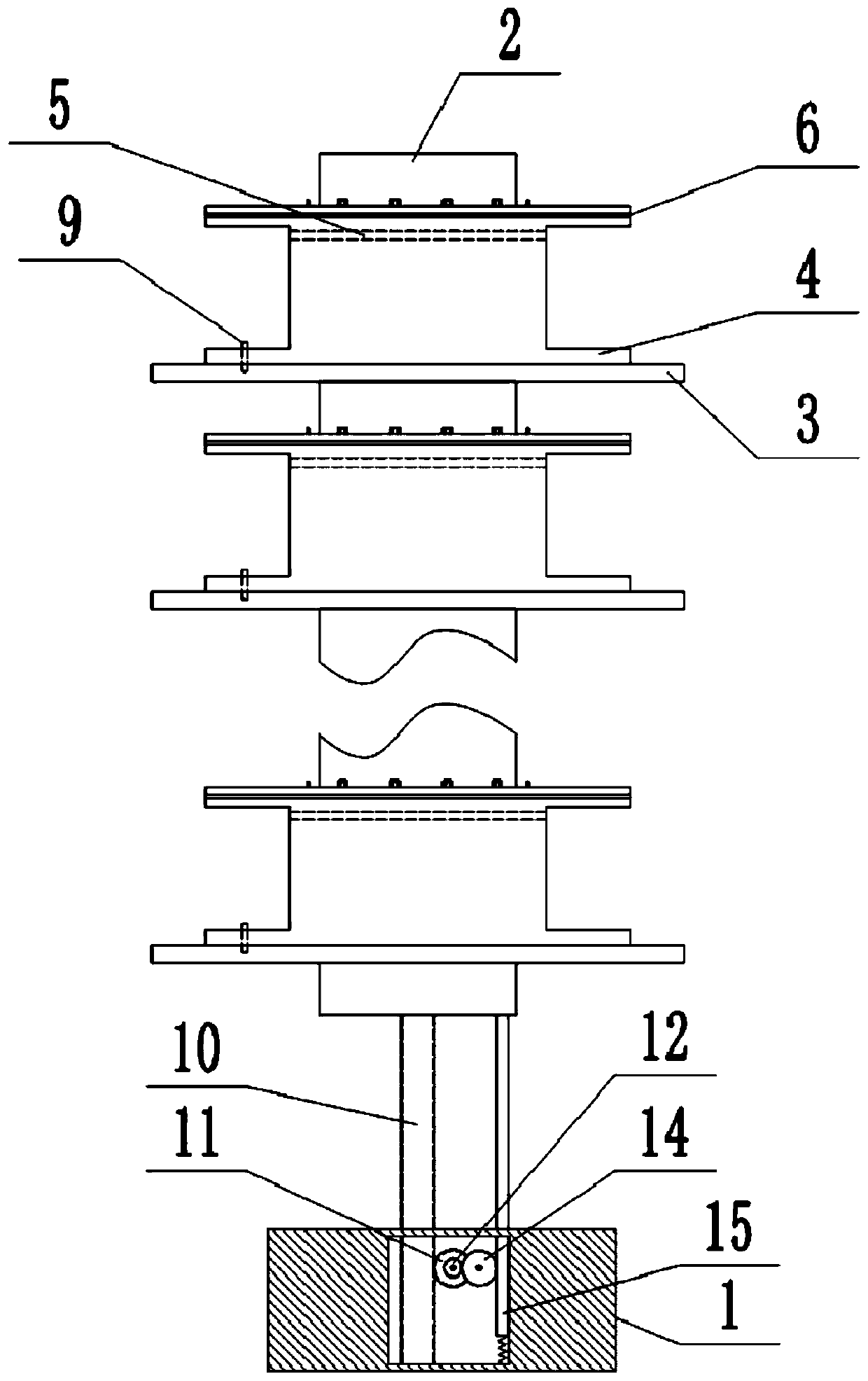
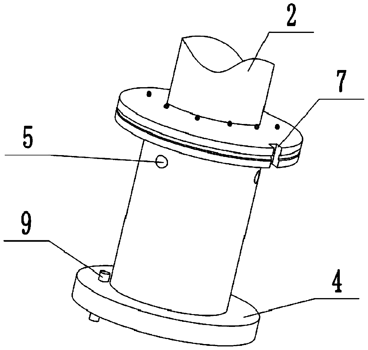
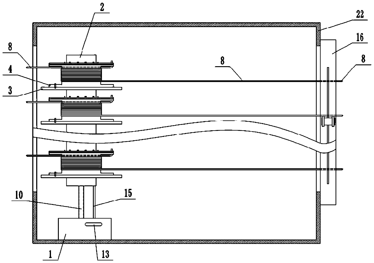
[0035] Line finishing device for electrical equipment, combined with attached figure 1 And attached figure 2 As shown, it mainly consists of a base 1, a rotating rod 2, several wire management and winding mechanisms, a driving mechanism, and a fastening mechanism. The base 1 is fixed in the housing 22 of the electrical equipment by means of screws or bonding. A cavity is provided in the base 1, and a driving mechanism for driving the rotating rod 2 to rotate is arranged in the cavity. The driving mechanism mainly consists of a worm screw 10, a second A rotating shaft, a worm wheel 11, and a push-up unit are formed, and the top of the worm 10 is connected with the bottom of the rotating rod 2 in a splined manner. The first rotating shaft is rotatably connected in the cavity, and one end of the first rotating shaft passes through the base 1 and is connected with a handle 13 . A worm wheel 11 is installed on the first rotating shaft, and the worm wheel 11 cooperates with the w...

Embodiment 2

[0046] The difference between this embodiment and embodiment 1 is that: image 3 And attached Figure 4 As shown, this embodiment also includes a fastening mechanism for fixing the drawn-out electric wires 8, and the fastening mechanism is arranged outside the electrical equipment casing 22 and near the wire outlet. The fastening mechanism is mainly composed of a column 16, a plurality of second through holes 17, and a tightening unit. The column 16 is fixed outside the housing 22 of the electrical equipment by means of screws or bonding, and the plurality of second through holes 17 are vertically uniform. Cloth on the column 16.

[0047] The jacking unit is used to fasten the electric wire 8. The jacking unit is mainly composed of several chutes, several jacking rods 18, a connecting rod 19 and a jacking assembly. Several chutes are set on the column 16. And each chute is correspondingly connected to a second through hole 17, and several ejector rods 18 are slidably connect...


PUM


Abstract

The invention relates to the technical field of electric equipment auxiliary tools, and discloses a line finishing device for electrical equipment. The line finishing device comprises a base, whereina rotating rod is rotationally connected to the base, a plurality of wire arranging and winding mechanisms are arranged on the rotating rod, each wire arranging and winding mechanism comprises a supporting disc fixed on the rotating rod, a wire winding shaft is rotationally connected to the supporting disc, the wire winding shaft sleeves the rotating rod, a torsion spring is arranged on the wire winding shaft, the end, away from the wire winding shaft, of the torsion spring is fixed on the rotating rod, a first through hole allowing electric wires to pass through is horizontally formed in thewire winding shaft, a pressing unit for pressing the head of the wire is arranged at the top of the wire winding shaft, a fixing unit used for fixing the wire winding shaft and the supporting disc together is further arranged on the wire winding shaft, a cavity is formed in the base, and a driving mechanism used for driving the rotating rod to rotate is arranged in the cavity. Compared with the prior art, the scheme can realize winding of multiple wires at the same time, the winding efficiency is high, the structure is simple, the occupied area is small, and the use is convenient.

Description

technical field [0001] The invention belongs to the technical field of electrical equipment auxiliary appliances. Background technique [0002] Due to the large number of internal components of electrical equipment, there are also many lines connected to each other, and there are also many lines connected to the outside. Usually, the wires enter from the inlet of the electrical equipment and are drawn out from the outlet of the electrical equipment, and the wires are connected in a disorderly manner in the housing of the electrical equipment, which affects the maintenance efficiency and appearance, and it is difficult for people to distinguish when using Which interface each wire should be connected to may cause the problem of wrong connection, which will cause the electrical equipment to malfunction or even be damaged. [0003] The existing wire management device is mainly composed of a base, a mounting frame, a through hole, and a winding roller. The wire is first passed ...

Claims


Application Information

Patent Timeline
IPC IPC(8): B65H75/38B65H75/44
CPCB65H75/38B65H75/44B65H75/4428B65H75/4492B65H2701/34
Inventor 梁康有谭宇航肖天伦周虹君
Owner CHONGQING UNIV OF ARTS & SCI
Learn More