
Accelerometer compensation method

An accelerometer and compensation method technology, applied in the direction of speed/acceleration/shock measurement, test/calibration of speed/acceleration/shock measurement equipment, measurement device, etc., can solve problems such as the reduction of accelerometer accuracy

Inactive Publication Date: 2020-04-10
BEIJING AUTOMATION CONTROL EQUIP INST
View PDF5 Cites 3 Cited by
  • Summary
  • Abstract
  • Description
  • Claims
  • Application Information

AI Technical Summary

Problems solved by technology

[0003] The purpose of the present invention is to overcome the deficiencies of the prior art and provide an accelerometer compensation method that can solve the problem of accelerometer accuracy reduction due to the influence of ambient temperature in the prior art

Method used


Image

  • Accelerometer compensation method
  • Accelerometer compensation method

Examples


Embodiment Construction

[0031] Specific embodiments of the present invention will be described in detail below in conjunction with the accompanying drawings. In the following description, for purposes of explanation and not limitation, specific details are set forth in order to provide a thorough understanding of the invention. It will be apparent, however, to one skilled in the art that the present invention may be practiced in other embodiments that depart from these specific details.

[0032] It should be noted here that, in order to avoid obscuring the present invention due to unnecessary details, only the device structure and / or processing steps closely related to the solution according to the present invention are shown in the drawings, and the steps related to the present invention are omitted. Invent other details that don't really matter.

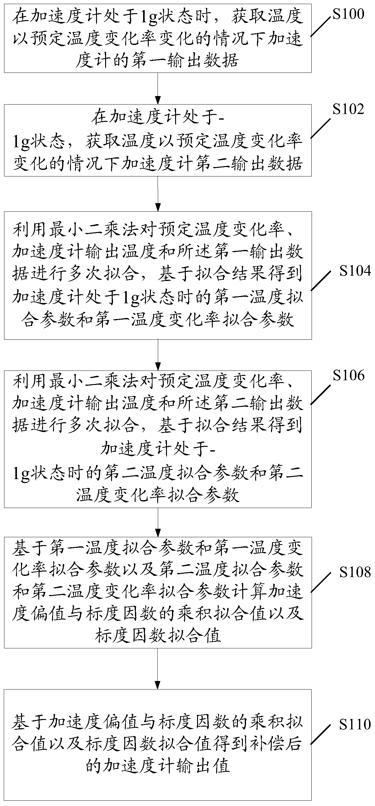
[0033] figure 1 It is a flowchart of an accelerometer compensation method provided by an embodiment of the present invention.

[0034] Such as figure...


PUM


Abstract

The invention relates to the technical field of inertia instrument manufacturing, and discloses an accelerometer compensation method. The method comprises the following steps: acquiring first output data when the temperature is changed at a predetermined temperature change rate at 1g; acquiring second output data when the temperature is changed at a predetermined temperature change rate at-1g; fitting the preset temperature change rate, the accelerometer output temperature and the first output data for multiple times, and obtaining a first temperature fitting parameter and a first temperaturechange rate fitting parameter at 1g based on a fitting result; fitting the preset temperature change rate, the accelerometer output temperature and the second output data for multiple times, and obtaining a second temperature fitting parameter and a second temperature change rate fitting parameter at-1g based on a fitting result; calculating a product fitting value and a scale factor fitting valueof the acceleration deviation value and the scale factor; and obtaining a compensated accelerometer output value based on the product fitting value of the acceleration offset value and the scale factor and the scale factor fitting value. Therefore, the temperature compensation effect of the accelerometer can be improved.

Description

technical field [0001] The invention relates to the technical field of inertial instrument manufacturing, in particular to an accelerometer compensation method. Background technique [0002] The accelerometer is the main component of the inertial navigation system. The performance of the accelerometer directly affects the accuracy of the inertial navigation system. Usually, the system performs comprehensive temperature calibration and establishes a temperature calibration model for the accelerometer, or uses a single accelerometer temperature calibration model. Under certain circumstances, the accuracy of the system can be well guaranteed. When the ambient temperature of the system changes rapidly, the accuracy of the accelerometer will decrease due to the temperature hysteresis characteristic of the accelerometer itself. Contents of the invention [0003] The purpose of the present invention is to overcome the deficiencies of the prior art, and provide an accelerometer co...

Claims


Application Information

Patent Timeline
Patent Type & Authority Applications(China)
IPC IPC(8): G01P21/00G01C25/00
CPCG01C25/005G01P21/00
Inventor 孙刚张菁华刘晓智丁凯梁文华杨星辉马高印
Owner BEIJING AUTOMATION CONTROL EQUIP INST
Learn More