
Fiber bragg grating displacement sensor

A technology of displacement sensor and optical fiber grating, which is applied in the direction of instruments, optical devices, and measuring devices, can solve the problems of reducing the measurement accuracy of the sensor, the change of the wavelength of the grating, and the large size of the sensor, so as to avoid inaccurate measurement, small size, The effect of improving sensitivity

Pending Publication Date: 2018-12-07
刘绍波
View PDF5 Cites 2 Cited by
  • Summary
  • Abstract
  • Description
  • Claims
  • Application Information

AI Technical Summary

Problems solved by technology

The existing fiber grating sensor has the following problems: pull the grating directly, fix one end of the grating, and connect the other end to the mobile end, but this method has a very small range (0.6mm), and it is easy to break the grating; the cantilever beam structure uses double optical fibers The grating is pasted on the upper and lower surfaces of the cantilever beam to achieve temperature compensation, but the size of the sensor in this method is large, and the wedge-shaped block is easy to cause vertical movement when sliding horizontally. Under the same horizontal displacement, the small movement in the vertical direction will change The deflection of the cantilever beam changes the wavelength of the grating and reduces the measurement accuracy of the sensor

Method used


Image

  • Fiber bragg grating displacement sensor
  • Fiber bragg grating displacement sensor

Examples


Embodiment

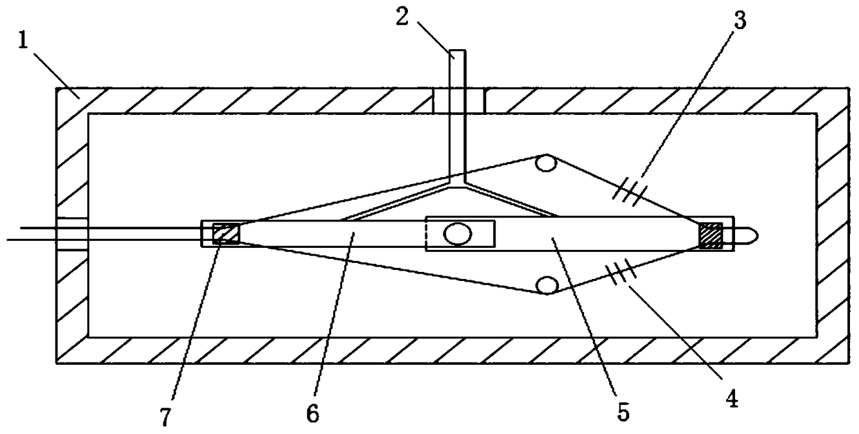
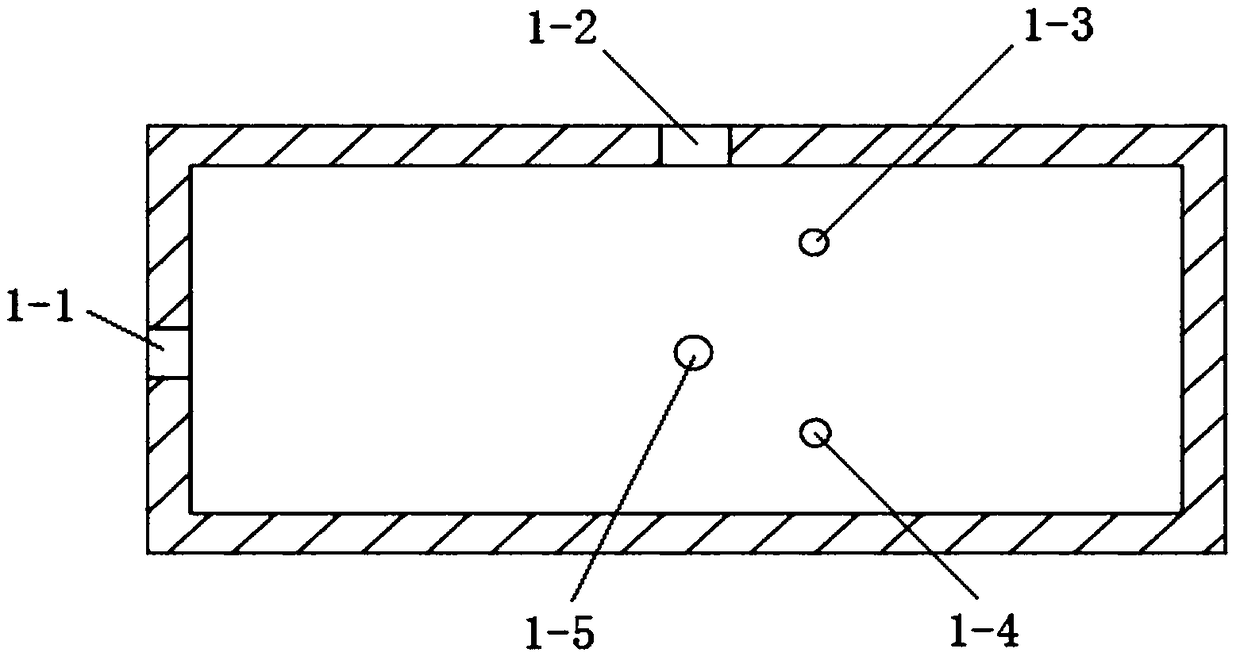
[0034] A fiber grating displacement sensor, which can change its shape arbitrarily according to the actual application. The push rod 2 is used to sense the external displacement change; it can reciprocate under the action of the built-in spring; The first rotating rod 5 and the second rotating rod 6 rotate freely around the third cylinder 1-5; The bottom will return with the reply of the push rod 2; the two ends of the first fiber grating 3 and the second fiber grating 4 bypass the first cylinder 1-3 and the second cylinder 1-4 respectively, and one end of the two gratings is welded for protection. And after pre-stretching, use adhesive 7 to fix their proper positions on the two ends of the first rotating rod 5 and the second rotating rod 6 respectively; tune the device. The specific detection process is as follows: when the external displacement changes, taking the displacement increase as an example, the push rod 2 pushes the first rotating rod 5 and the second rotating rod...


PUM


Abstract

The present invention discloses a fiber bragg grating displacement sensor. The displacement sensor comprises a substrate, a push rod, a first fiber bragg grating, a second fiber bragg grating, a firstrotation rod and a second rotation rod; one side of the substrate is provided with an fiber output hole, the upper side of the substrate is provided with an upper through hole, the middle portion ofthe internal portion of the substrate is provided with a first cylinder, a second cylinder and a third cylinder which is located at the center of the substrate, and the first cylinder and the second cylinder are respectively located at the upper and lower sides of the third cylinder; one ends, connected to each other, of the first rotation rod and the second rotation rod are fixed at the top portion of the third cylinder, and the other ends thereof are hung in the air; the rotation rods freely rotate around the third cylinder under the action of the push rod; and the two ends of the first fiber bragg grating and the second fiber bragg grating bypass the first cylinder and the second cylinder to be fixed at the two ends of the first rotation rod and the second rotation rod; and the pigtailof the optical fiber is led out through the fiber output hole. The fiber bragg grating displacement sensor is high in sensitivity, anti-electromagnetic interference, free of signal distortion, simplein structure and high in stability, can perform long-term real-time online monitoring.

Description

technical field [0001] The invention belongs to the technical field of optical fiber sensing, and in particular relates to an optical fiber grating displacement sensor. Background technique [0002] Displacement monitoring is one of the most basic measurement items in structural health monitoring. Real-time monitoring of displacement plays an important role in the deformation, cracking and sliding monitoring of major structures such as mechanical equipment and civil engineering. At present, traditional electrical sensors are the most widely used in displacement monitoring, but electrical sensors have disadvantages such as susceptibility to electromagnetic interference, poor stability, difficulty in long-term real-time monitoring, and easy to be affected by complex and harsh field working environments. It is difficult to guarantee the measurement accuracy, and it does not have the functions of long-distance monitoring and data transmission, which greatly limits the applicatio...

Claims


Application Information

Patent Timeline
Patent Type & Authority Applications(China)
IPC IPC(8): G01B11/02
CPCG01B11/02
Inventor 刘绍波
Owner 刘绍波
Learn More