
Video image blind denoising method used in mine shaft environment

A video image and wellbore technology, which is applied in the field of blind denoising of video images, can solve the problems that the noise cannot be removed well, the denoising effect is not ideal, and the denoising effect of the video image of the mine shaft is not ideal.

Active Publication Date: 2020-04-10
WUHAN UNIV OF SCI & TECH
View PDF4 Cites 4 Cited by
  • Summary
  • Abstract
  • Description
  • Claims
  • Application Information

AI Technical Summary

Problems solved by technology

However, the existing image denoising algorithm has a good denoising effect on noisy images with known noise levels, but the denoising effect on mine shaft video images with unknown noise levels is not ideal.
It often happens that when the noise variance estimate is too small, the noise cannot be removed well, and when the noise variance estimate is too large, the image details after denoising will appear blurred.
[0004] In addition, from the perspective of timeliness, image denoising is a relatively time-consuming process. The existing traditional denoising methods need to calculate the similarity between each pixel in the image and several pixels in the search window, or image Divide into several image blocks and find several similar image blocks in the search window, and use these pixels or image blocks to perform weighted average to achieve image denoising
The size of the search window directly affects the time complexity of the algorithm. A small search area has a small amount of calculation but poor denoising performance, while a larger search area has better denoising performance but increases the amount of calculation.
The existing image denoising algorithm does not use the redundant information between the frames of the wellbore video image, resulting in high algorithm complexity and unsatisfactory denoising effect

Method used

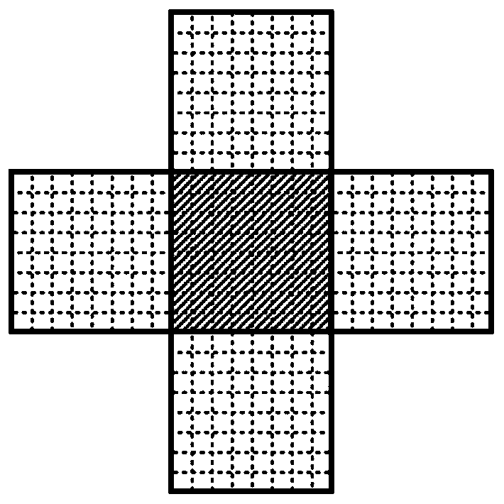
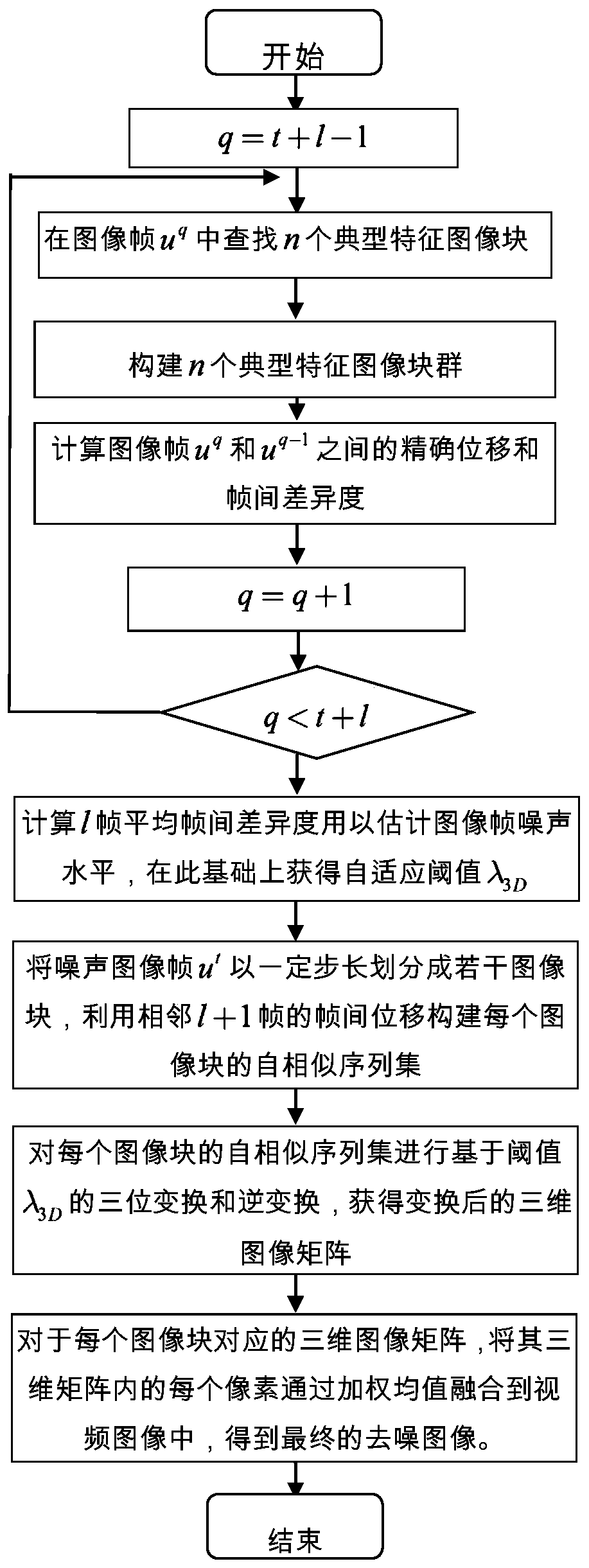
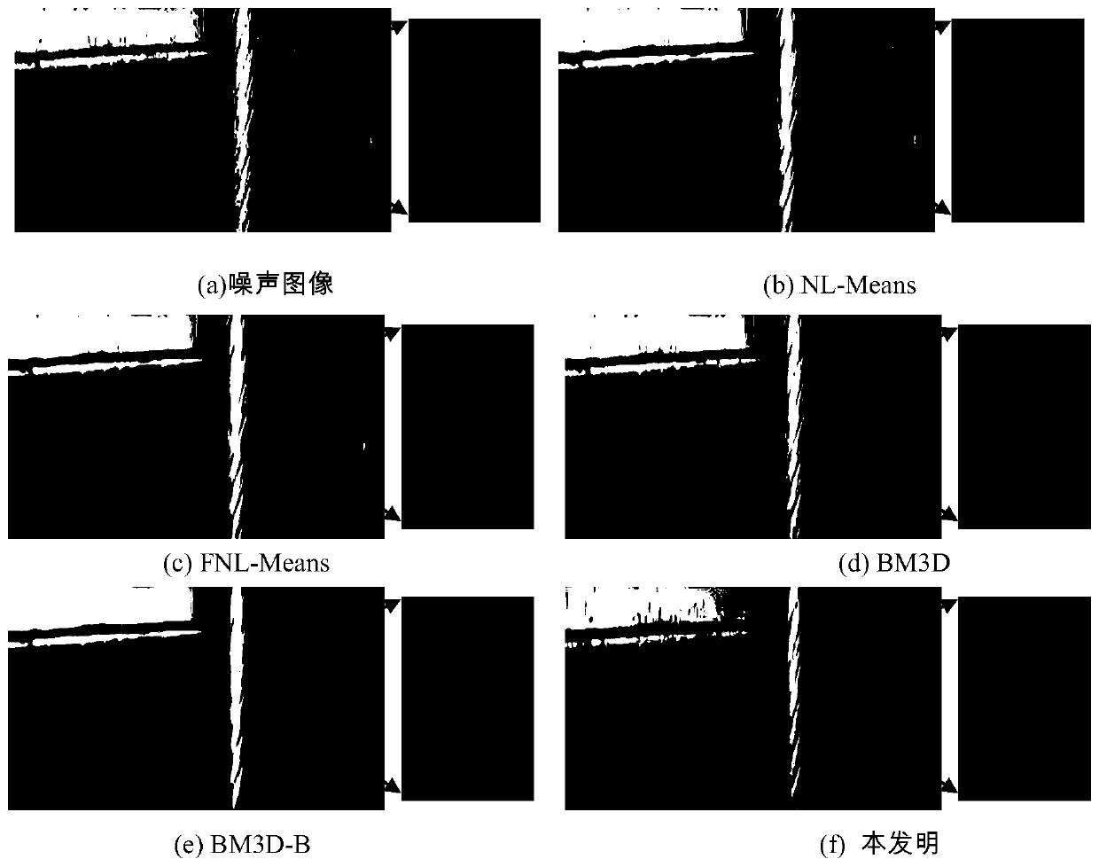

Image

  • Video image blind denoising method used in mine shaft environment
  • Video image blind denoising method used in mine shaft environment
  • Video image blind denoising method used in mine shaft environment

Examples


Embodiment Construction

[0058] The technical solution of the present invention will be described in detail below in conjunction with the drawings and embodiments.

[0059] The technical solution of the present invention can adopt computer software technology to realize the automatic operation process. The process of a method for blindly denoising video images in the mine shaft environment provided by the embodiment includes the following steps in sequence:

[0060] 1. Find typical feature image blocks on the image to be denoised, and construct typical feature block groups according to the block group structure

[0061] The present invention utilizes typical feature image blocks to construct feature block groups, which are used to quickly locate precise displacements between frames, so as to quickly build self-similar sequence sets of image blocks, thereby improving the time efficiency and signal-to-noise ratio of denoising. However, in practical applications, the jitter and non-uniform motion of the ...


PUM


Abstract

The invention relates to a video image blind denoising method used in a mine environment. The method comprises the following steps of: selecting a plurality of image frames adjacent to a to-be-denoised video image in front of and behind the to-be-denoised video image, searching an image block group with typical characteristics in each image frame, and determining inter-frame accurate displacementby searching a block group having the minimum difference degree with the image block group in a previous frame of image; dividing the to-be-denoised video image into a plurality of image blocks, and quickly constructing a self-similarity sequence set of each image block according to the inter-frame accurate displacement; combining two-dimensional image blocks corresponding to the self-similarity sequence set into a three-dimensional matrix, performing three-dimensional transformation, and performing adaptive threshold filtering on a transformation coefficient; and aggregating the three-dimensional matrix which has been subjected to three-dimensional inverse transformation to generate a denoised image. The execution efficiency of the algorithm is improved, and meanwhile. Compared with a denoised image obtained by an existing image denoising method, the denoised image obtained by the method of the invention has a better signal-to-noise ratio and a better visual effect.

Description

technical field [0001] The invention relates to the technical fields of mine shaft safety and digital image processing, in particular to a method for blindly denoising video images in the mine shaft environment. Background technique [0002] With the development of image processing technology, splicing and recognition of the collected video images of mine shaft facilities, and quickly and accurately judging whether there is a fault in the equipment has attracted attention. , the video images of facilities collected by camera technology contain more noise, which affects the accuracy of automatic analysis and identification of subsequent wellbore facility failures. Denoising noisy images is a fundamental and critical problem in the fields of digital image processing and computer vision. Specifically, noise often appears as isolated pixels or pixel blocks that cause strong visual effects on images. Image denoising refers to the process of reducing noise in digital images. [...

Claims


Application Information

Patent Timeline
IPC IPC(8): G06T5/00G06T7/223G06T7/246G06T7/285
CPCG06T7/223G06T7/246G06T7/285G06T5/70
Inventor 邢远秀李军贤龚谊承王文波
Owner WUHAN UNIV OF SCI & TECH
Learn More