

Microwave device cavity, microwave device and antenna
Patent Information
- Authority / Receiving Office
- CN · China
- Patent Type
- Applications(China)
- Current Assignee / Owner
- COMBA TELECOM TECH (GUANGZHOU) CO LTD
- Publication Date
- 2020-04-10
Smart Images
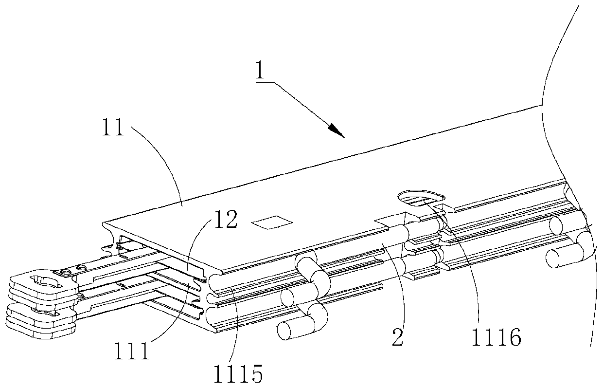
Figure 1 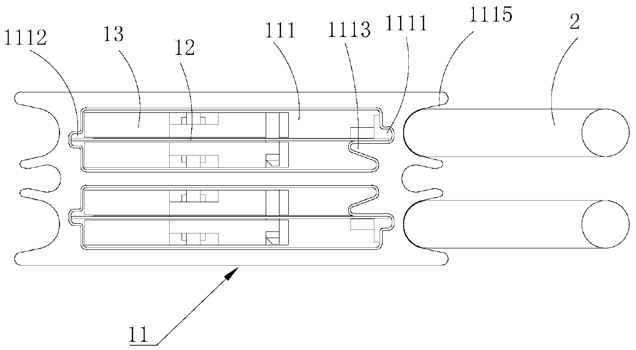
Figure 2 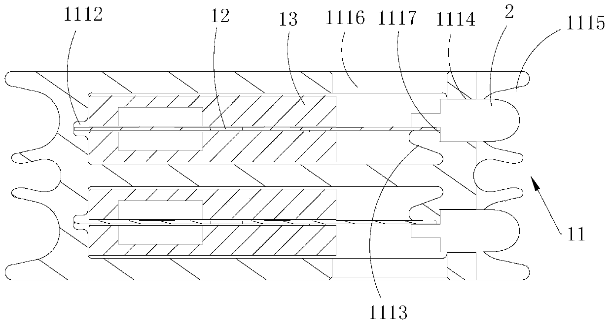
Figure 3
Abstract
Description
technical field
[0001] The invention relates to the technical field of mobile communication, in particular to a microwave device cavity, a microwave device and an antenna. Background technique
[0002] At present, the cost pressure of base station antennas continues to increase, but the requirements for product stability are also increasing, and providing a low-cost and high-stability antenna has become a mainstream development trend. Among them, reducing the total cost of antenna products by reducing the thickness of the circuit board inside the phase shifter is one of the more common solutions, and the thickness of the circuit board can be reduced to 0.2mm. However, because the cavity generally adopts the production method of pultrusion, a circuit board slot with a thickness of 0.2 mm cannot be formed in the cavity. When the circuit board is inserted into the circuit board slot, due to the difference in thickness between the circuit board and the slot Matching, there is a...