Discharge friction generator

A technology of friction generator and friction layer, applied in the direction of friction generator, etc., can solve the problem of lack of output capacity of friction generator, and achieve the effect of simple and controllable material system, low production cost and simple structure

Active Publication Date: 2020-04-10
XIDIAN UNIV
View PDF6 Cites 5 Cited by
  • Summary
  • Abstract
  • Description
  • Claims
  • Application Information

AI Technical Summary

Problems solved by technology

[0004] Although the existing research has demonstrated the super adaptability of the friction generator in different working environments and its high output performance, there are still many obstacles that cannot be ignored in the practical application of the friction generator.
First, after changing the friction surface of the generator from a planar structure to a surface with a micro-nano structure, we seem to lack a more effective method for further improving the output capacity of the friction generator

Method used


Image

  • Discharge friction generator
  • Discharge friction generator
  • Discharge friction generator

Examples


Embodiment 1

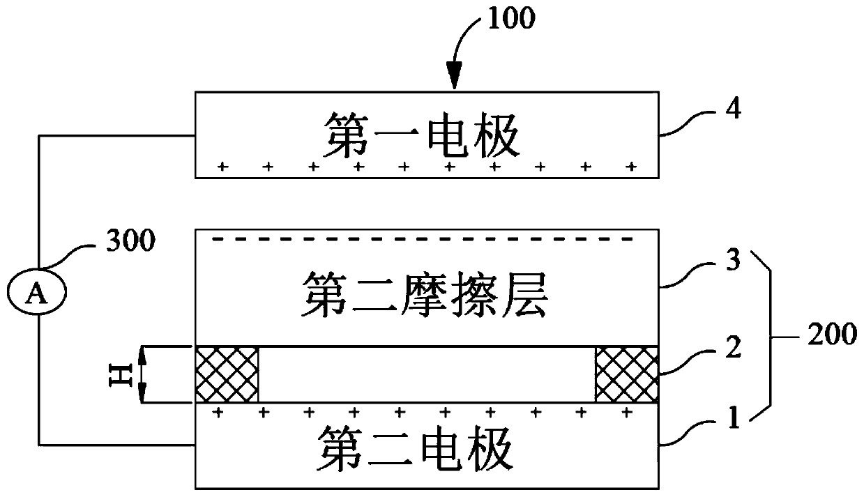
[0035] figure 1 shows a schematic structural diagram of a discharge friction generator of the present invention, please refer to figure 1 , the discharge friction generator includes a first friction unit 100, including a first electrode 4; a second friction unit 200, including a second friction layer 3 and a second electrode 1, and the second electrode 1 is arranged on the second The surface of the friction layer 3 away from the first friction unit 100; wherein, a first preset interval H is reserved between the second electrode 1 and the second friction layer 3, and the second friction layer 3 and the first electrode 4 are respectively located in different positions of the electrostatic sequence.

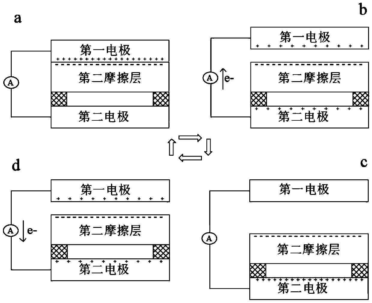
[0036] It should be noted, figure 1 The shown discharge friction generator works in vertical contact-separation mode, but it should be understood that the technical solution of this embodiment is also applicable to discharge friction generators in other working modes such as slidi...

Embodiment 2

[0058] Image 6 A schematic structural diagram of the second discharge friction generator of the present invention is shown. see Image 6 , the discharge triboelectric generator includes: a first friction unit 100', including a first electrode 4' and a first friction layer 6', and the first electrode 4' is disposed far below the first friction layer 6' The surface of the second friction unit 200' to be introduced; the second friction unit 200' includes a second friction layer 3' and a second electrode 1', and the second electrode 1' is arranged on the second friction layer 3' The surface away from the first friction unit 100'; wherein, a first preset interval H1 is reserved between the first electrode 4' and the first friction layer 6', and the second friction layer 3 ' and the first electrode 4' are respectively located in different positions of the electrostatic sequence.

[0059] It should be noted, Image 6 The shown discharge friction generator works in vertical conta...


PUM

PropertyMeasurementUnit
thicknessaaaaaaaaaa

Abstract

The invention provides a discharge friction generator, the working mode of which can adopt a vertical contact-separation mode or a sliding mode, the discharge friction generator comprising: a first friction unit comprising a first electrode; a second friction unit comprising a second friction layer and a second electrode, and the second electrode is arranged on the surface, away from the first friction unit, of the second friction layer; wherein a first preset interval is reserved between the second electrode and the second friction layer, and the position of the material of the second friction layer is different from the position of the material of the first electrode in the electrostatic sequence. According to the discharge friction generator, the frictional charge induction effect is enhanced by changing different contact distances between the friction layer in the friction generator and the electrodes of the friction layer, so that more high-density currents are generated by large-scale discharge during operation, and electric signals generated by triboelectrification and the discharge effect are coupled and cooperatively output.

Description

technical field [0001] The invention relates to the technical field of functional devices, in particular to a discharge friction generator. Background technique [0002] At present, the world's main energy consumption is petroleum, coal and other non-renewable resources. Facing the contradiction between people's increasing energy demand and the world's limited energy reserves, the development and utilization of clean energy has become the consensus of the times. Clean energy includes wind energy, water energy, tidal energy and other non-polluting and sustainable energy sources. The effective utilization of clean and renewable resources has become an important issue related to world peace and economic development. [0003] As the world enters the era of the Internet of Things (IoT) and artificial intelligence, multifunctional arrays of sensing systems will form the hardware foundation of the fourth industrial revolution, moving toward functionality and intelligence. Given ...

Claims


Application Information

Patent Timeline
Patent Type & Authority Applications(China)
IPC IPC(8): H02N1/04
CPCH02N1/04
Inventor 崔暖洋李鑫
Owner XIDIAN UNIV
Why Eureka
Try Eureka