Temporary monitoring equipment

A monitoring equipment and temporary technology, applied in mechanical equipment, TV, color TV, etc., can solve the problems of inconvenient adjustment of cameras, troublesome transfer of temporary monitoring equipment, etc., to achieve the effect of convenient transfer and convenient adjustment

Active Publication Date: 2020-04-10
山东尚美网络科技有限公司
View PDF15 Cites 5 Cited by
  • Summary
  • Abstract
  • Description
  • Claims
  • Application Information

AI Technical Summary

Problems solved by technology

At present, the security devices in the community mainly include camera monitoring. Usually, the camera monitoring in the community is placed at a fixed location. When setting up, it is troublesome to transfer the temporary monitoring equipment, and because the monitoring equipment is generally three or four meters high, it is inconvenient to adjust the position of the camera

Method used


Image

  • Temporary monitoring equipment
  • Temporary monitoring equipment
  • Temporary monitoring equipment

Examples


Embodiment Construction

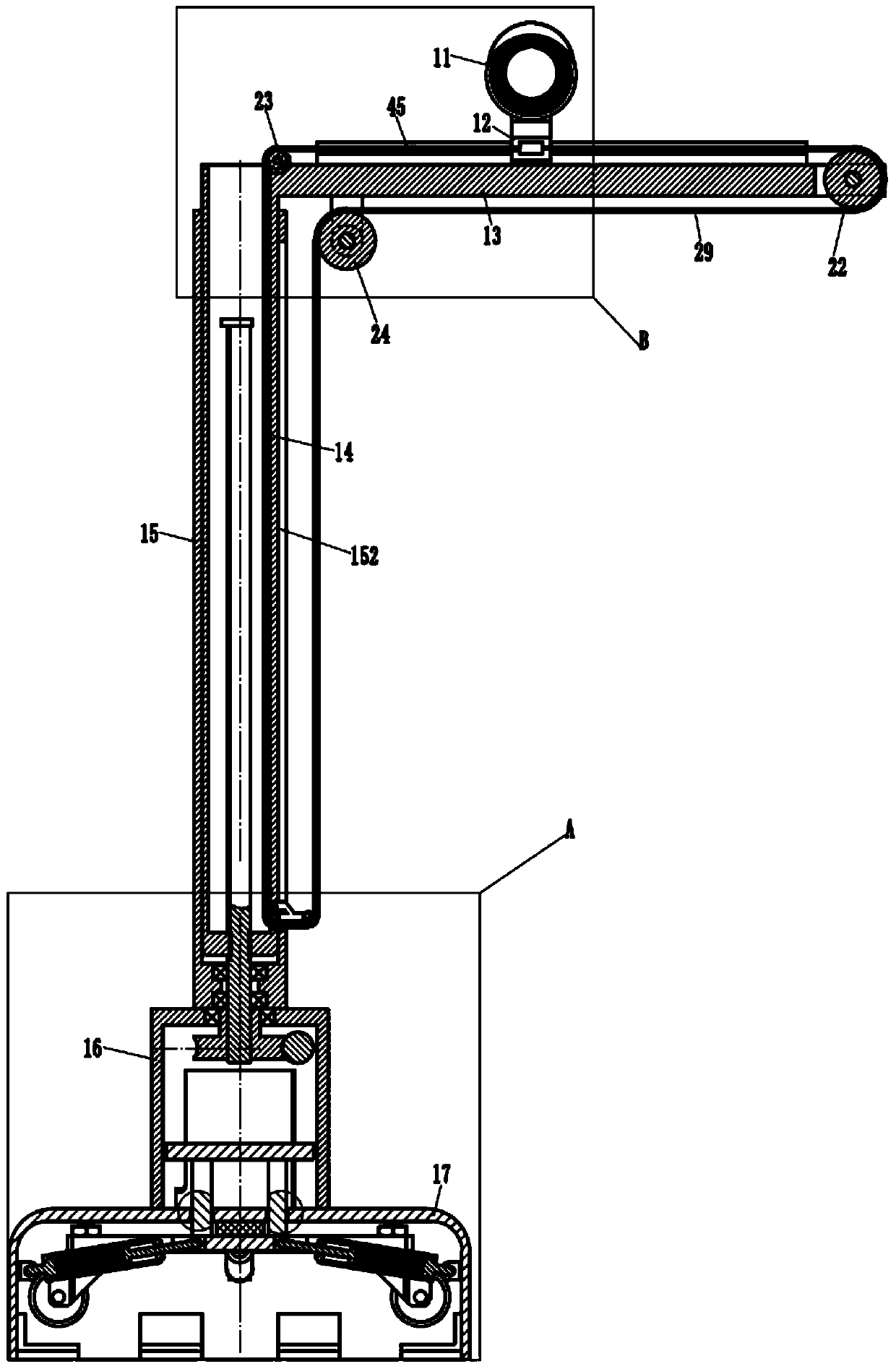
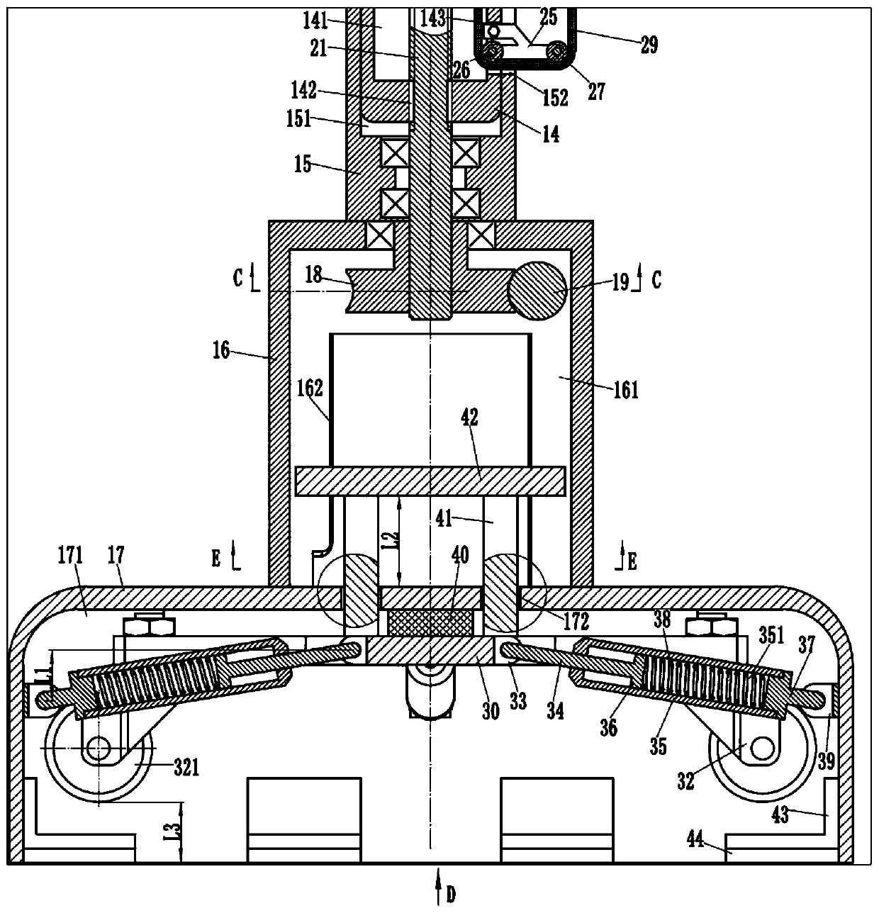
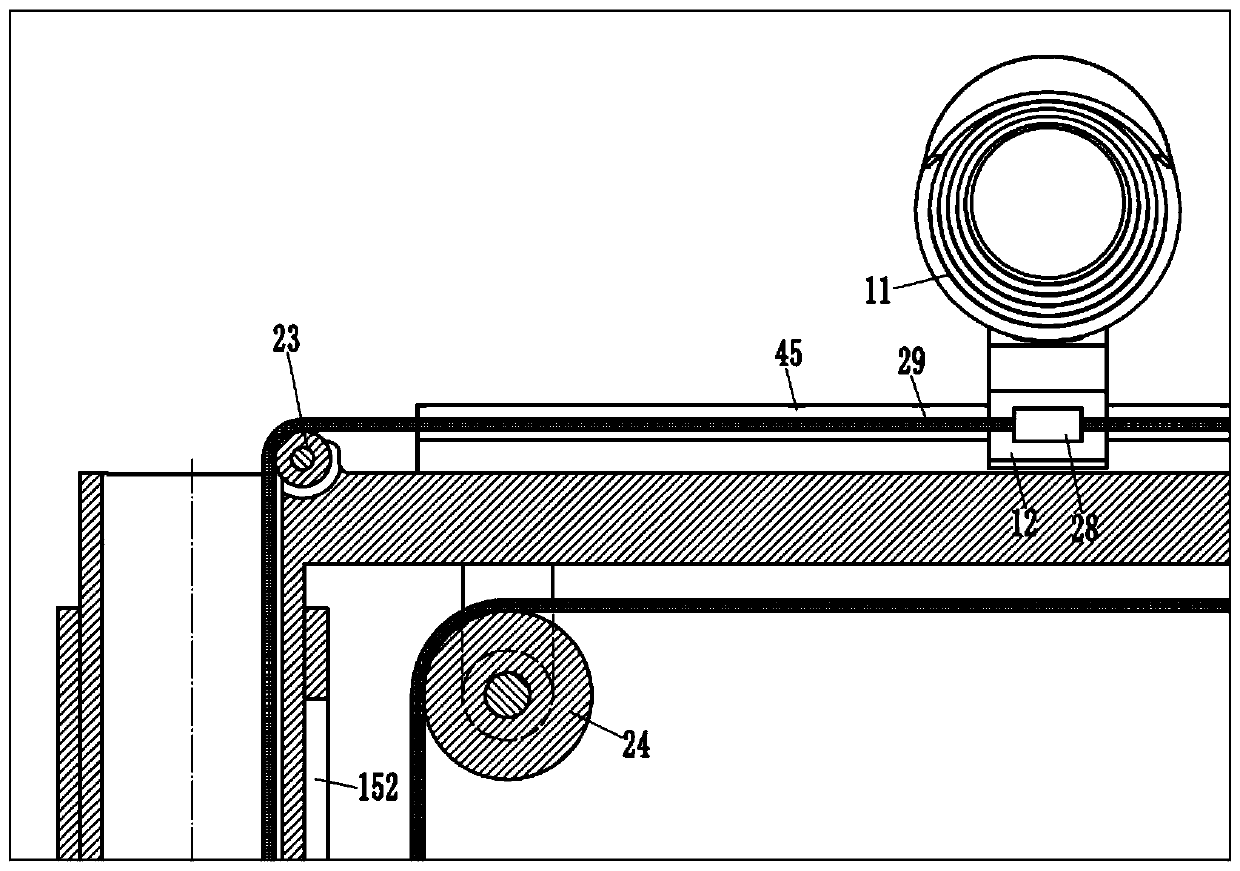
[0018] Examples, see e.g. Figure 1 to Figure 7 As shown, a kind of temporary monitoring equipment comprises camera 11, and described camera 11 is fixed on the slide block 12, and slide block 12 inserts sleeve on the slide rail 45 that left and right direction is provided with, and slide rail 45 is fixed on the crossbeam 13, and crossbeam 13 The left end of the left end is fixed on the outer wall of the upper end of the rectangular lifting column 14, the rectangular lifting column 14 is inserted into the rectangular hole 151 of the rectangular column 15, the rectangular column 15 is fixed on the upper end of the driving seat 16, and the driving seat 16 is fixed on the base 17. The driving seat 16 is formed with a circular cavity 161 with an opening on the lower side. A turbine 18 is sleeved in the circular cavity 161. The turbine 18 is hinged on the upper side wall of the circular cavity 161. A worm 19 is engaged on one side of the turbine 18. The worm 19 is hinged on the On t...


PUM


Abstract

The invention discloses a temporary monitoring device. The device comprises a camera, the camera is fixed to a sliding block of a cross beam, the sliding block is connected through a rope, the cameracan move left and right through a traction rope, the cross beam is fixed to the upper end of a rectangular lifting column, the rectangular lifting column can ascend and descend through a screw, a baseis arranged below the rectangular lifting column, and universal wheels capable of popping up are arranged in the base. The universal wheels can move downwards to protrude out of the base, transferring is convenient, and the position of the camera is convenient to adjust.

Description

Technical field: [0001] The invention relates to the technical field of security products, in particular to a temporary monitoring device. Background technique: [0002] As we all know, the community camera monitoring device is a device used for security protection in the community. It is widely used in various residential, work and other areas and places. The protection of community security is to better serve people and ensure the safety of people's personal and property. To maintain social stability, community security is of paramount importance. At present, the security devices in the community mainly include camera monitoring. Usually, the camera monitoring in the community is placed at a fixed location. When setting up, the transfer of temporary monitoring equipment is more troublesome, and because the monitoring equipment is generally three or four meters high, it is inconvenient to adjust the position of the camera. Invention content: [0003] The purpose of the ...

Claims


Application Information

Patent Timeline
Patent Type & Authority Applications(China)
IPC IPC(8): H04N5/225H04N7/18G03B17/56F16M11/04F16M11/18F16M11/42
CPCH04N7/18G03B17/561F16M11/045F16M11/046F16M11/18F16M11/42H04N23/50
Inventor 胡惠娟
Owner 山东尚美网络科技有限公司
Why Eureka
Try Eureka