Rotating assembly, armrest and seat
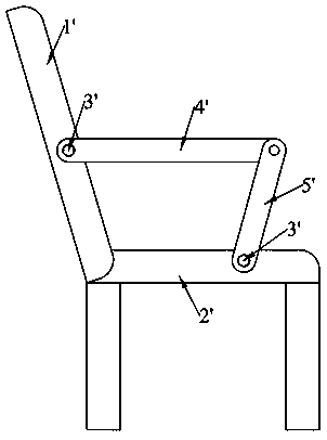
A technology of rotating components and rotating parts, applied in chairs, other seating furniture, stools, etc., can solve the problems of loose bolts, shaking of the second plate 5, and easy loosening of bolts 3', so as to achieve less loosening and improve stability. sexual effect
- Summary
- Abstract
- Description
- Claims
- Application Information
AI Technical Summary
Problems solved by technology
Method used
Image

Examples
Example Embodiment
[0034] Example 1
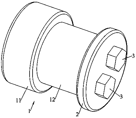
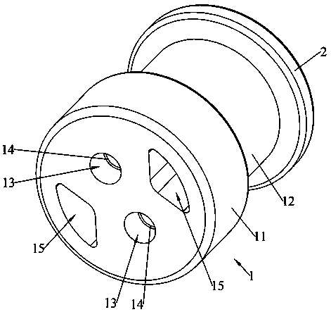
[0035] This embodiment provides a rotating assembly, such as Figure 2-Figure 5 As shown, the rotating assembly includes a rotating member 1, a blocking cover 2 and a locking member 3. The rotating member 1 includes a first cylindrical section 11 and a second cylindrical section 12 arranged in the axial direction. The shaft diameter of the first cylindrical section 11 is larger than that of the first cylindrical section 11. The diameter of the two cylindrical sections 12 is larger than that of the second cylindrical section 12 , and the blocking cover 2 is detachably connected to the outer end surface of the second cylindrical section 12 through the locking member 3 .
[0036] The rotating assembly can be applied to occasions where articulation is required. For example, if the first part and the second part need to be hinged, first connect the first cylindrical segment 11 to the first part, and after the second cylindrical segment 12 passes through the seco...
Example Embodiment
[0049] Embodiment 2
[0050] This embodiment provides a connecting assembly, an armrest and a seat. The difference between this embodiment and the first embodiment is that in this embodiment, the connecting hole 13 is provided with an embedded nut 14 , the locking member 3 is a screw, and the screw passes through the blocking cover 2 and is connected with the embedded nut 14 . By arranging the embedded nut 14, the processing requirements of the rotating member 1 are reduced, the processing of the rotating member 1 is more convenient, and the degree of cooperation with the screw is higher.
Example Embodiment
[0051] Embodiment 3
[0052] This embodiment provides a connecting assembly, an armrest and a seat. The difference between this embodiment and Embodiment 1 and Embodiment 2 is that: Figure 10 and Figure 11 As shown, in this embodiment, the end surface of the second cylindrical section 12 is provided with a groove 16 , and the end surface of the blocking cover 2 is provided with a convex strip 22 matched with the groove 16 . Since the second part (ie, the first plate 4 or the second plate 5 ) generates a circumferential frictional force on the blocking cover 2 when it rotates relative to the second cylindrical section 12 , the grooves 16 and the protruding strips 22 are arranged to cooperate with each other. , which can better limit the circumferential rotation of the blocking cover 2 , avoid screw loosening, and ensure a firm connection between the blocking cover 2 and the second cylindrical section 12 .
PUM
 Abstract
Description
Claims
Application Information
 - R&D Engineer
- R&D Manager
- IP Professional
- Industry Leading Data Capabilities
- Powerful AI technology
- Patent DNA Extraction
Browse by: Latest US Patents, China's latest patents, Technical Efficacy Thesaurus, Application Domain, Technology Topic.
© 2024 PatSnap. All rights reserved.Legal|Privacy policy|Modern Slavery Act Transparency Statement|Sitemap