
A mechanical arm mechanism for tumor resection

A robotic arm and tumor technology, applied in the field of intelligent equipment, can solve problems such as the improvement of the control method of the robotic arm, and achieve the effects of simple and flexible fine-tuning methods, wide application ranges, and flexible adjustment methods

Active Publication Date: 2020-09-18
HENAN CANCER HOSPITAL
View PDF17 Cites 0 Cited by
  • Summary
  • Abstract
  • Description
  • Claims
  • Application Information

AI Technical Summary

Problems solved by technology

[0005] The patent notification number is CN108175509B, a surgical robot operating end moving device. In its technical scheme, an arc is set at the connecting end of the mechanical arm, and the connecting end of the mechanical arm moves in the arc, and then the mechanical arm works. The fine-tuning of the relative position of the front and rear ends of the manipulator does not improve the control method of the manipulator itself, but only indirectly realizes the position adjustment of the working end of the manipulator by changing the movement mode of the joint end of the manipulator.

Method used


Image

  • A mechanical arm mechanism for tumor resection
  • A mechanical arm mechanism for tumor resection
  • A mechanical arm mechanism for tumor resection

Examples


Embodiment 1

[0034] A mechanical arm mechanism for tumor resection, comprising an operating arm body, one end of the operating arm body is provided with an instrument installation end, and the other end is connected with a transmission connector; a fine-tuning mechanism is arranged in the middle of the operating arm body.

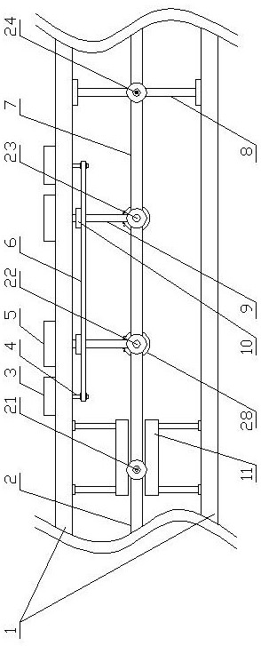
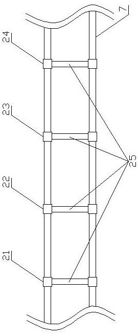
[0035] fine-tuning mechanism such as Figure 1-10 As shown; the fine-tuning mechanism includes an outer frame body 1 and a linkage fine-tuning structure 2 arranged in the outer frame body 1, the position of the instrument mounting end is fine-tuned by the linkage fine-tuning structure 2, and the large-scale position adjustment of the instrument mounting end still adopts the prior art in X , Y, and Z-axis directions for large-scale adjustment, this kind of fine-tuning is only for fine-tuning the front and rear distances of the instrument installation end, the linkage fine-tuning structure 2 is connected to the instrument installation end at one end, and the other end is c...

Embodiment 2

[0043] Such as Figure 11 As shown, compared with Embodiment 1, in this embodiment, an auxiliary telescopic rod 13 is connected below the first lifting shaft 22 and the second lifting shaft 23, and the auxiliary telescopic rod 13 is fixed on the inner wall of the outer frame body 1 Above, it can assist the first lifting shaft 22 and the second lifting shaft 23 to keep stable, and the auxiliary telescopic rod 13 can use a spring telescopic rod or a sleeve type telescopic tube to assist the first lifting shaft 22 and the second lifting shaft 23 The up and down displacement always maintains the vertical state.

Embodiment 3

[0045] Such as Figure 12 As shown, compared with Embodiment 1, this embodiment has three connecting shafts in this embodiment, which are respectively a moving shaft, a lifting shaft and a fixed shaft, wherein the lifting shaft can move upwards in the vertical direction.


PUM


Abstract

The invention belongs to the technical field of intelligent equipment, relates to a surgical robot, and particularly discloses a mechanical arm mechanism for tumor excision. The mechanical arm mechanism comprises a surgical arm body, an instrument mounting end is arranged at one end of the surgical arm body, and the other end is connected with a transmission connecting piece. A fine adjustment mechanism is arranged in the middle of the surgical arm body. The fine adjustment mechanism comprises an outer frame body and a linkage fine adjustment structure arranged in the outer frame body, one endof the linkage fine adjustment structure is connected with the instrument mounting end, and the other end is connected with the transmission connecting piece. The linkage fine adjustment structure isof a double-chain structure, one end of the double-chain structure is fixed, the other end of the double-chain structure is movable, and the double-chain structure in the middle is foldable. The mechanical arm mechanism is simple in structure, high in adjusting precision and good in stability.

Description

technical field [0001] The invention belongs to the technical field of intelligent equipment, and relates to a surgical manipulator, in particular to a manipulator mechanism for tumor resection. Background technique [0002] At present, in the field of tumor treatment, if robotic resection is used, da Vinci robots are mostly used. After a certain amount of training, the surgeon operates the robotic arm system on the console and observes it through the imaging system. [0003] In the robotic arm system of a surgical robot, it usually includes multiple instrument arms and camera arms, and the robotic arms can be offset and rotated in the three directions of X, Y, and Z, that is, there is a "6+1 degree of freedom instrument design". ", two-way movement on the three coordinate axes, coupled with the free movement of the "hand" connected to the end of the mechanical arm, the other end of the mechanical arm is connected to the connecting piece and driven by the connecting piece to...

Claims


Application Information

Patent Timeline
Patent Type & Authority Patents(China)
IPC IPC(8): A61B34/30
CPCA61B34/30A61B34/70A61B34/77
Inventor 荣方方
Owner HENAN CANCER HOSPITAL
Learn More