
Vehicle radar imaging method and device, electronic equipment

A technology of vehicle-mounted radar and imaging method, applied in the field of vehicle-mounted radar, can solve the problems of inability to complete near and far-end joint imaging processing, reduce image processing efficiency, etc., and achieve the effect of easy engineering implementation, less hardware resources, and avoiding zero-filling operations.

Active Publication Date: 2021-11-30
BEIJING AUTOROAD TECH CO LTD
View PDF0 Cites 0 Cited by
  • Summary
  • Abstract
  • Description
  • Claims
  • Application Information

AI Technical Summary

Problems solved by technology

[0005] Embodiments of the present invention provide a vehicle-mounted radar imaging method and device, and electronic equipment, to at least solve the problem that vehicle-mounted radars in related technologies can only use remote imaging or near-end imaging, and cannot complete near-distal joint imaging processing, reducing image processing efficiency. technical issues

Method used


Image

  • Vehicle radar imaging method and device, electronic equipment
  • Vehicle radar imaging method and device, electronic equipment
  • Vehicle radar imaging method and device, electronic equipment

Examples


Embodiment 1

[0045] The vehicle-mounted radar imaging method described below is applied to a target vehicle equipped with a synthetic aperture radar (SAR).

[0046] According to an embodiment of the present invention, an embodiment of a vehicle-mounted radar imaging method is provided. It should be noted that the steps shown in the flowcharts of the accompanying drawings can be executed in a computer system such as a set of computer-executable instructions, and, although A logical order is shown in the flowcharts, but in some cases the steps shown or described may be performed in an order different from that shown or described herein.

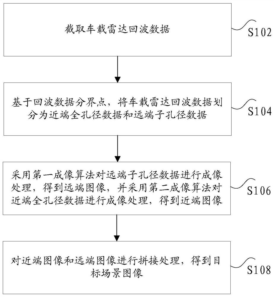
[0047] figure 1 is a flow chart of an optional vehicle-mounted radar imaging method according to an embodiment of the present invention, such as figure 1 As shown, the method includes the following steps:

[0048] Step S102, intercepting vehicle radar echo data;

[0049] Step S104, based on the echo data demarcation point, divide the vehicle radar echo d...

Embodiment 2

[0136] The present invention will be described below in conjunction with another optional embodiment.

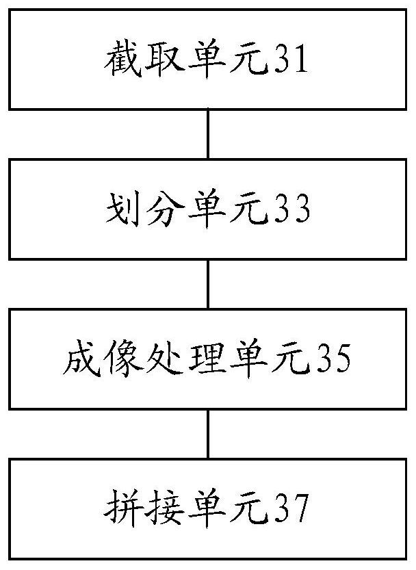
[0137] image 3 is a schematic diagram of an optional vehicle-mounted radar imaging device according to an embodiment of the present invention, such as image 3 As shown, the vehicle-mounted radar imaging device includes: an intercepting unit 31, a dividing unit 33, an imaging processing unit 35, and a splicing unit 37, wherein,

[0138] An intercepting unit 31, configured to intercept vehicle-mounted radar echo data;

[0139] A division unit 33, configured to divide the vehicle radar echo data into near-end full-aperture data and far-end aperture data based on the echo data demarcation point;

[0140] The imaging processing unit 35 is configured to perform imaging processing on the distal end aperture data by using the first imaging algorithm to obtain a far end image, and use a second imaging algorithm to perform imaging processing on the near end full aperture data to o...


PUM


Abstract

The invention discloses a vehicle-mounted radar imaging method and device, and electronic equipment. Wherein, the method includes: intercepting the vehicle radar echo data; dividing the vehicle radar echo data into near-end full aperture data and far-end aperture data based on the echo data demarcation point; Imaging processing, obtaining a far-end image, and performing imaging processing on the near-end full-aperture data by using a second imaging algorithm to obtain a near-end image; splicing the near-end image and the far-end image to obtain a target scene image. The invention solves the technical problem that in the related art, the vehicle-mounted radar can only use the far-end imaging or the near-end imaging, and cannot complete the near-distal joint imaging processing, which reduces the image processing efficiency.

Description

technical field [0001] The present invention relates to the technical field of vehicle radar, in particular, to a vehicle radar imaging method and device, and electronic equipment. Background technique [0002] In related technologies, vehicle-mounted SAR is a new mode of automotive radar at present. Through two-dimensional imaging processing of radar echoes, images that can reflect the two-dimensional geometric configuration of characteristic targets are obtained. [0003] At present, common SAR is characterized by narrow beam width in azimuth, long action distance and long synthetic aperture length. When performing imaging processing with a fixed azimuth width, all azimuth apertures are sub-apertures or full apertures, and only full-aperture imaging algorithms or sub-aperture imaging algorithms are used to complete two-dimensional imaging processing. The vehicle-mounted SAR is obviously different from the ordinary SAR. It is characterized by a wider beam width in azimuth,...

Claims


Application Information

Patent Timeline
Patent Type & Authority Patents(China)
IPC IPC(8): G01S13/90
CPCG01S13/9005G01S13/90
Inventor 郭鑫唐侃梁小伟
Owner BEIJING AUTOROAD TECH CO LTD
Learn More