Supercharge Your Innovation With Domain-Expert AI Agents!

A large tolerance floating connector and connector assembly

A floating connector, large-tolerance technology, applied in the parts, connections, contact parts of the connecting device, etc., can solve the problems of being equivalent to another arm, unreliable contact connection, etc., to achieve large-tolerance capability, The effect of extensive utilization of value and cost reduction

Active Publication Date: 2021-07-30
CHINA AVIATION OPTICAL-ELECTRICAL TECH CO LTD
View PDF5 Cites 0 Cited by
  • Summary
  • Abstract
  • Description
  • Claims
  • Application Information

AI Technical Summary

Problems solved by technology

In fact, the BusBar shifts a certain distance to apply force to one of the conductive sheets, and the conductive sheet then transmits the force to one arm of the U-shaped spring clip. Due to the limitation of the U-shaped spring clip structure, it is impossible to effectively equalize the force on one arm. effect on the other arm, which causes the force on the conductive sheet on the side that is offset from the BusBar to be less than the force applied to the conductive sheet by the BusBar, that is, the displacement of the conductive sheet opposite to the moving direction of the BusBar is less than the displacement of the conductive sheet in the moving direction of the BusBar , when the displacement difference is greater than the cumulative error of the BusBar, it is easy to cause unreliable contact connection

Method used


Image

  • A large tolerance floating connector and connector assembly
  • A large tolerance floating connector and connector assembly
  • A large tolerance floating connector and connector assembly

Examples


Embodiment Construction

[0046] In order to further explain the technical means and effects of the present invention to achieve the intended purpose of the invention, the specific implementation, structure, characteristics and details of the large-tolerance floating connector proposed according to the present invention will be described below in conjunction with the accompanying drawings and preferred embodiments. Its effect is described in detail below.

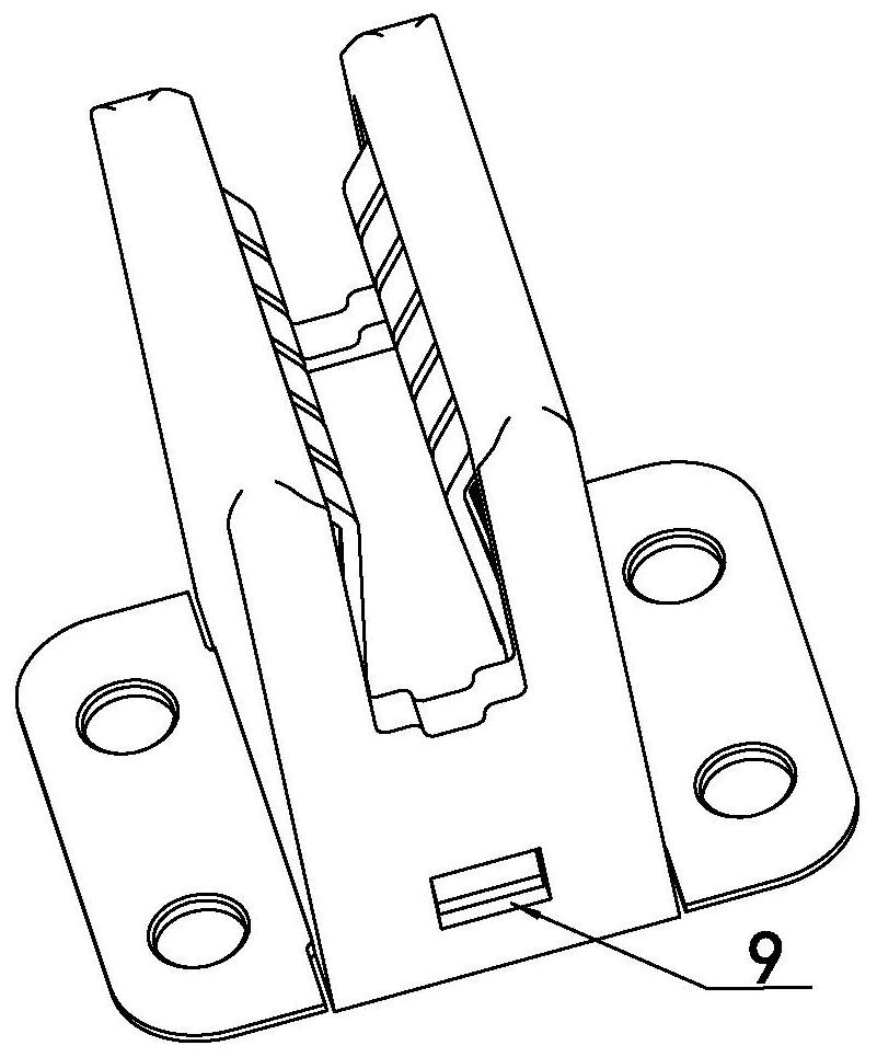
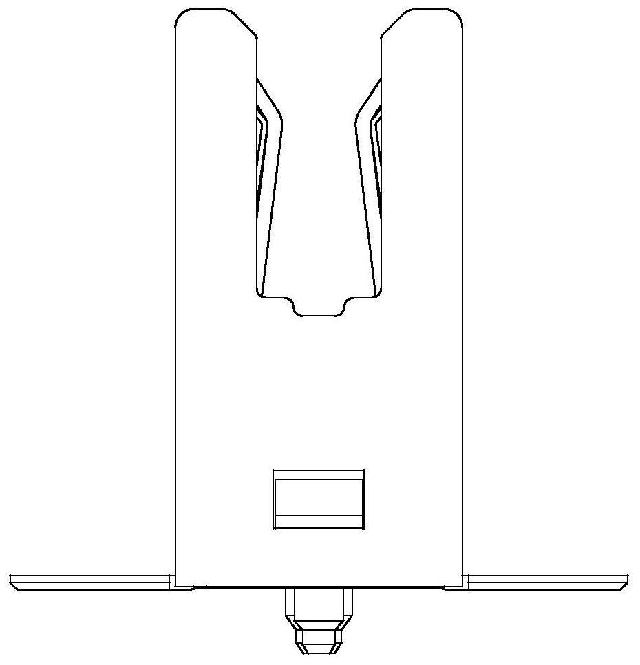
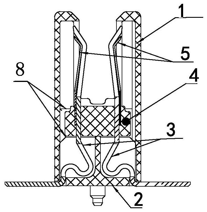
[0047] see Figure 1-8 , which is a structural diagram of each part of the large-tolerance floating connector of the present invention, the connector includes an insulating housing 1 and a jack part located in the insulating housing 1, and the jack part includes two sets of conductive sheets arranged at intervals relative to each other 3. The conductive sheet 3 is sequentially provided with one or more contact parts, a fixed part, a flexible bending part that can realize floating, and a mounting part that extends out of the insulating shell and conn...


PUM


Abstract

The invention relates to a floating connector with large tolerance, which includes an insulating shell and two sets of oppositely arranged conductive sheets located in the insulating shell, and the two sets of conductive sheets include at least one relative bend from top to bottom to form a busbar for insertion into The contact part of the jack, the fixed part that limits the relative position of the two conductive sheets, the flexible part that realizes the up and down floating, and the installation part that protrudes out of the insulating shell and connects with the printed board or copper bar; the fixed part of the two sets of conductive sheets passes through the slider The conductive piece-slider part is relatively fixed. When the connector is mated eccentrically, the conductive piece on the side with strong force of the conductive piece-slider part drives the conductive piece on the weak side to move synchronously through the fixed part, thus ensuring The socket formed by the contact part of the conductive sheet is stable and constant, and the force on both sides is even. The present invention locks the conductive piece with the wedge-shaped groove through the slider, so that the slider and the conductive piece are completely matched. When the force is applied, the conductive piece moves along with the slider along a predetermined track, thereby ensuring that the connector has greater tolerance.

Description

technical field [0001] The invention relates to the technical field of connectors, in particular to a large-tolerance floating connector and a connector assembly. Background technique [0002] In server design, it is often necessary to connect the power module to the motherboard for current transmission. With the increase of the server's requirements for the flow capacity of the unit space, it is usually transmitted from the power module to the connector in the form of a bus bar; the connector is transmitted to the printed board or copper busbar by welding or solderless to supply power for it . With the commercialization of 5G, the performance requirements of connectors in the market are getting higher and higher. In this way, a connector with high current and large tolerance has emerged as the times require. [0003] Existing connectors are usually composed of a pair of conductive sheets and a U-shaped elastic member. The elastic member can rotate around the U-shaped bott...

Claims


Application Information

Patent Timeline
Patent Type & Authority Patents(China)
IPC IPC(8): H01R13/02H01R13/40H01R13/631H01R24/00
CPCH01R13/02H01R13/40H01R13/6315H01R24/00
Inventor 张荣团李猛冯冲翟超杰程升升
Owner CHINA AVIATION OPTICAL-ELECTRICAL TECH CO LTD
Features
  • R&D
  • Intellectual Property
  • Life Sciences
  • Materials
  • Tech Scout
  • Unparalleled Data Quality
  • Higher Quality Content
  • 60% Fewer Hallucinations
Learn More