Device capable of being used for regulating glass

An adjustable glass technology, applied in the field of doors and windows, can solve the problems of sagging and inability to adjust the doors and windows, and achieve the effect of reducing maintenance costs and facilitating disassembly

Inactive Publication Date: 2020-04-17
GUANGDONG COLOGNE OEZER TECH CO LTD
View PDF0 Cites 0 Cited by
  • Summary
  • Abstract
  • Description
  • Claims
  • Application Information

AI Technical Summary

Problems solved by technology

like figure 1 As shown, the adjustable glass spacers on the market are two wedge-shaped structural blocks. Adjust the height of the glass spacers before installation. After installation, the door and window sash can not be adjusted.

Method used


Image

  • Device capable of being used for regulating glass
  • Device capable of being used for regulating glass
  • Device capable of being used for regulating glass

Examples


Embodiment 1

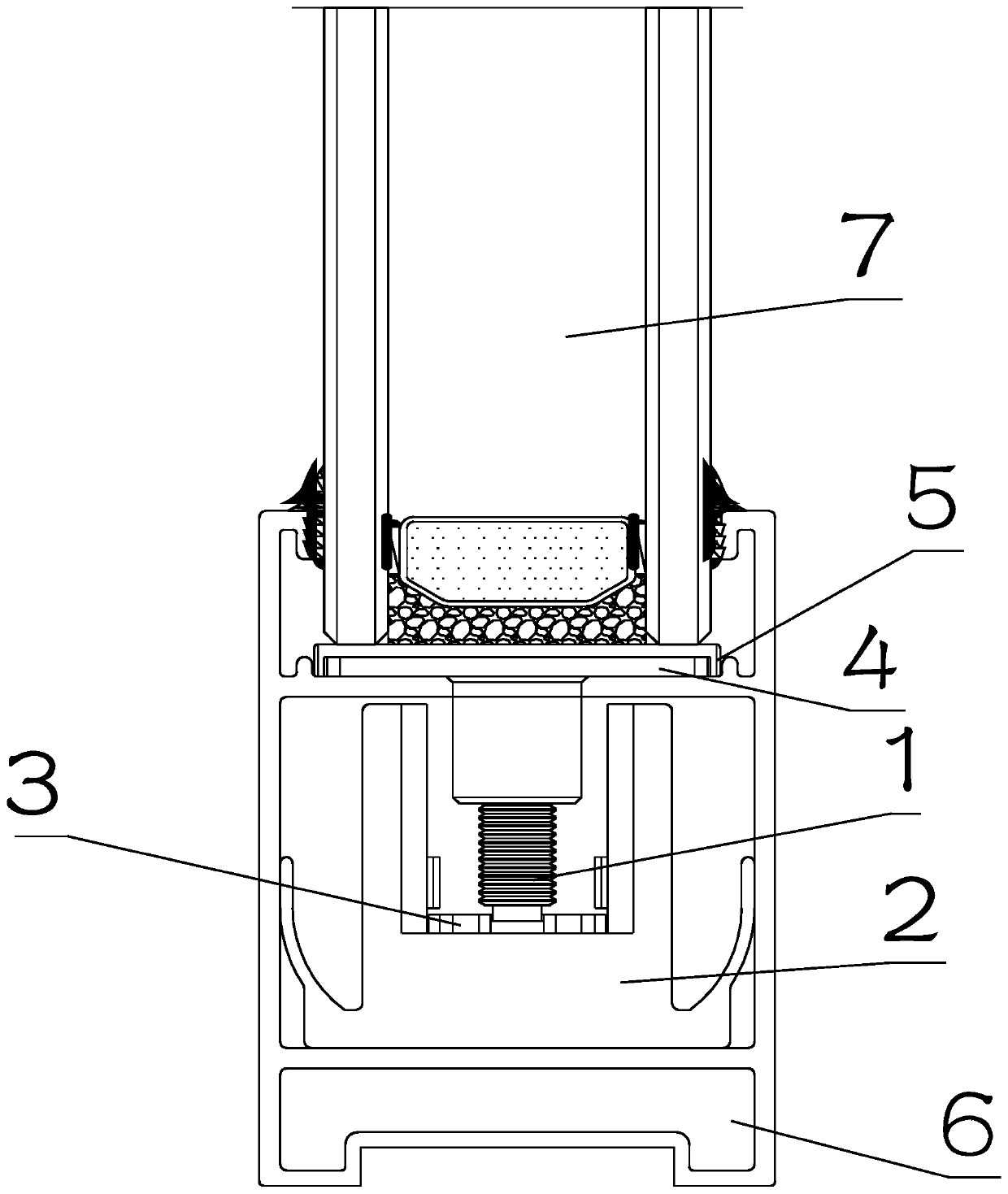
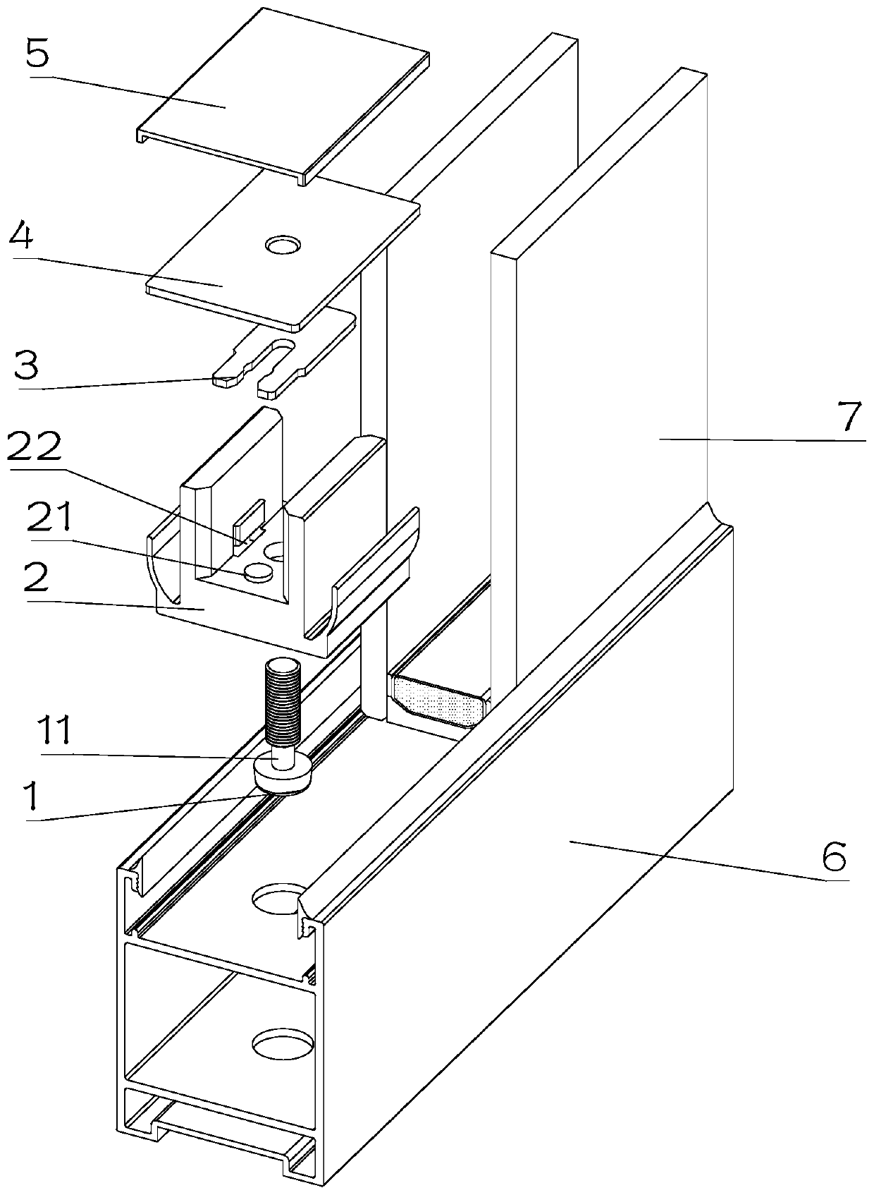
[0021] see figure 2 , 3 , in Embodiment 1 of the present invention, an adjustable glass device includes a lining block 2 fixedly arranged inside the door leaf 6; a movable part 4 arranged up and down inside the door leaf 6, and the upper part of the movable part 4 is in contact with the glass 7 On, the movable part 4 is set for resisting the glass;

[0022] Wherein, a countersunk screw 1 is rotatably installed on the pad 2, and the upper end of the countersunk screw 1 is rotatably installed in a threaded hole on the movable part 4, and the door leaf 6 is provided with an adjustment hole for driving the countersunk screw 1 to rotate. . When the door and window sash appeared to sag, tools could be used to rotate the driving countersunk screw 1 at the adjustment hole, and the countersunk screw 1 drives the movable part 4 to move for adjustment.

Embodiment 2

[0024] see figure 2 , 3 The main difference between this embodiment 2 and embodiment 1 is that the lining block 2 is provided with a through hole 1 for installing the countersunk screw 1, the countersunk screw 1 is provided with a slot 11, and the clamping plate 3 Clamped on slot one 11, the clamping plate 3 is fixedly installed on the lining block 2; so that the countersunk screw 1 can only rotate on the lining block 2 and cannot move up and down.

[0025] The clamping plate 3 is provided with an opening for clamping on the first slot 11 .

[0026] Both sides of the clamping plate 3 are stuck in the slot 2 22 on the lining block 2, and the positioning column 21 on the lining block 2 is arranged in the positioning groove on the opening; Removal and installation for easy maintenance.

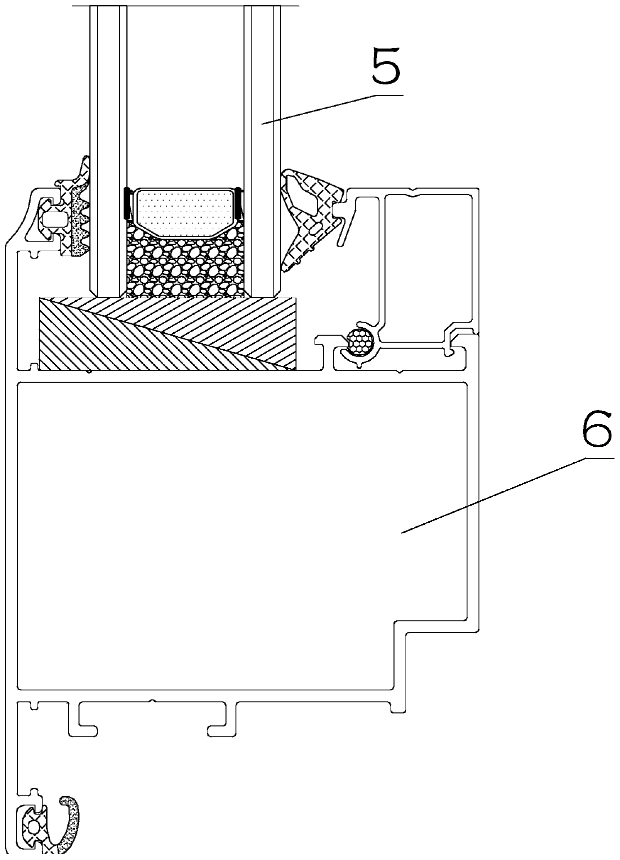
[0027] A glass block 5 made of soft material is also arranged between the movable part 4 and the door leaf 6 for protecting the door leaf 6 .

[0028] The glass block 5 is made of soft rubbe...


PUM


Abstract

The invention discloses a device capable of being used for regulating glass, and relates to the technical field of doors and windows. The device capable of being used for regulating glass comprises alining block and a moving element, wherein the lining block is fixedly arranged inside a door leaf; the moving element is vertically and movably arranged inside the door leaf; the upper part of the moving element is abutted against the glass; a countersunk screw is rotationally arranged on the lining block; the upper end of the countersunk screw is rotationally arranged in a threaded hole formed in the moving element; and a regulating hole used for driving the countersunk screw to rotate is formed in the door leaf. The device capable of being used for regulating glass has the advantages that when the door leaf or a window sash generates a drooping phenomenon, the countersunk screw can be rotated in the position of the regulating hole by a tool; the countersunk screw drives the moving element to move; further, the glass is regulated; and the after-sale maintenance cost of the doors and windows is greatly reduced.

Description

technical field [0001] The invention relates to the technical field of doors and windows, in particular to an adjustable glass device. Background technique [0002] After the doors and windows are used for a period of time, it is often found that the door and window sash is caused by the deviation of the glass position. In light cases, the sealing of the doors and windows will deteriorate, and the overall performance of the doors and windows will decline; in severe cases, the opening and closing of the doors and windows will be difficult and cannot be used. To solve this problem, a device with adjustable glass was designed. like figure 1 As shown, the adjustable glass spacers on the market are two wedge-shaped structural blocks. The height of the glass spacers can be adjusted before installation. If the door and window sashes sag after installation, the adjustment cannot be performed. The adjustable glass device can also adjust the glass after the door and window are assem...

Claims


Application Information

Patent Timeline
Patent Type & Authority Applications(China)
IPC IPC(8): E06B3/66E06B3/58
CPCE06B3/5864E06B3/6621
Inventor 朱福庆
Owner GUANGDONG COLOGNE OEZER TECH CO LTD
Why Eureka
Try Eureka