Pneumatic pipeline transmission system and transmission method thereof

A technology of transmission system and pneumatic pipeline, which is applied in the field of pipeline transmission system, can solve the problems that affect the normal use of customers, the door body and its control mechanism are easily damaged, and the system failure rate is high, so as to save the electric control mechanism and the failure rate is low , The effect of simple system structure

Inactive Publication Date: 2010-07-14
BEIJING RINRONG TECH
View PDF5 Cites 5 Cited by
  • Summary
  • Abstract
  • Description
  • Claims
  • Application Information

AI Technical Summary

Problems solved by technology

[0006] The existing door body that opens the transceiver opening or seals the transceiver opening is controlled by an electric control mechanism to open and close it. Due to the complexity

Method used


Image

  • Pneumatic pipeline transmission system and transmission method thereof
  • Pneumatic pipeline transmission system and transmission method thereof
  • Pneumatic pipeline transmission system and transmission method thereof

Examples


Embodiment 1

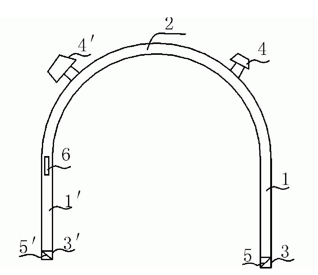
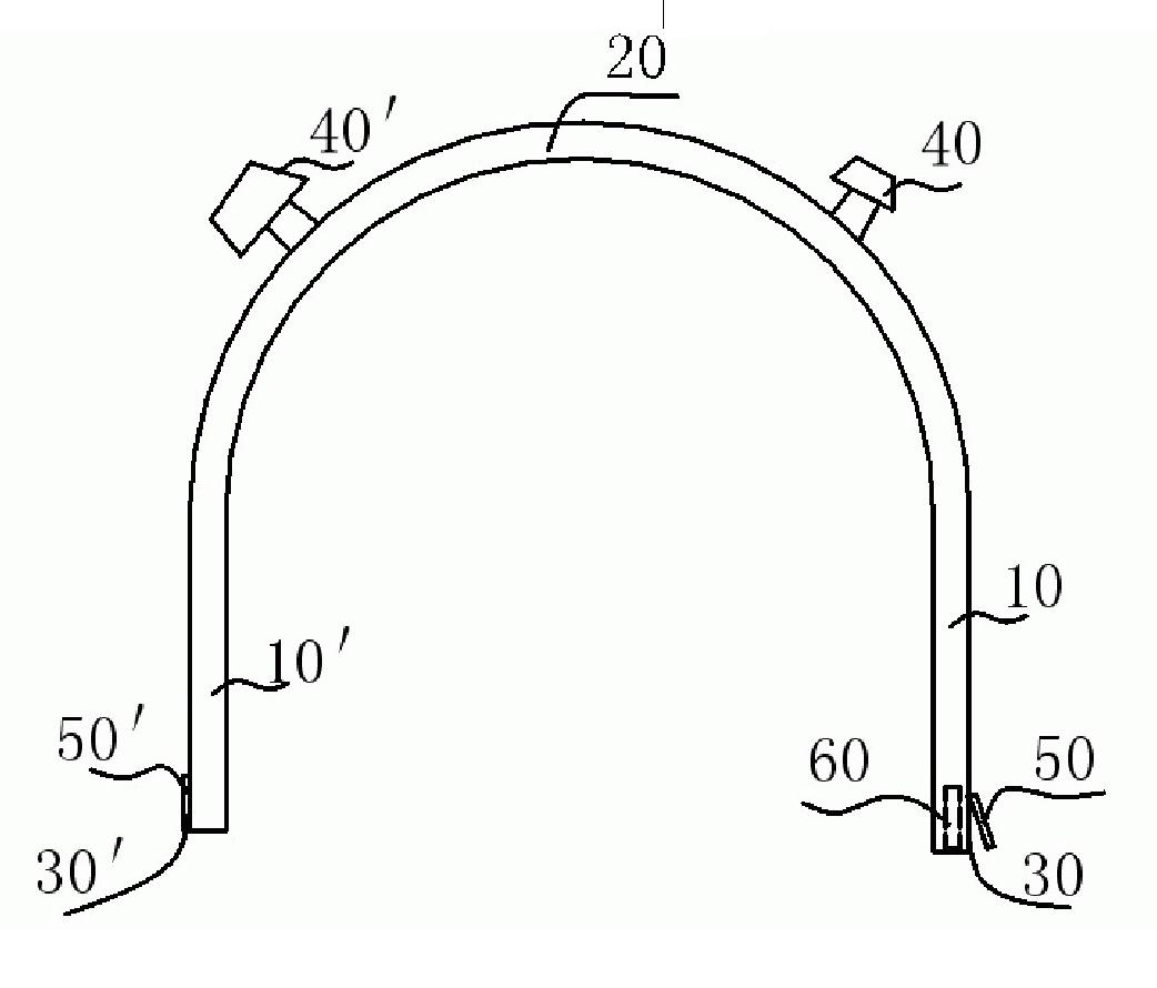
[0055] refer to figure 2 As shown, the pneumatic pipeline transmission system of the embodiment of the present invention includes a transmission pipeline, and the transmission pipeline includes two vertical pipelines 10, 10', and a top connecting the two vertical pipelines 10, 10' Curved pipe 20; the lower ends of the vertical pipes 10, 10' are provided with receiving and receiving openings 30, 30'; the lower ends of the vertical pipes are closed, and the receiving and receiving openings 30, 30' are arranged On the pipe side walls of the lower ends of the vertical pipes 10, 10'; on the curved pipe 20, near the tops of the vertical pipes 10, 10' are respectively provided with exhaust devices 40, 40'; Door bodies 50, 50' are pivotally connected to the top sides of the receiving and receiving openings 30, 30' at the lower ends of the vertical pipes 10, 10'. Adaptation: an air inlet is also provided at the lower end of each of the vertical pipes 10, 10', and the air inlet is an ...

Embodiment 2

[0061] refer to Figure 5 , Figure 6 As shown, the pneumatic pipeline transmission system of the present invention includes a transmission pipeline, and the transmission pipeline includes three vertical pipelines 10, 10', 10", and the top of the three vertical pipelines 10, 10', 10" A curved pipe 20 connected to each other; the lower ends of the vertical pipes are provided with receiving and receiving openings 30, 30', 30", and the receiving and receiving openings are the lower ends of the vertical pipes 10, 10', 10". flush ports;

[0062] Ventilation devices 40, 40', 40" are respectively provided at positions near the tops of the vertical ducts 10, 10', 10" on the curved duct; in the vertical ducts 10, 10', The door bodies 50, 50', 50" are pivotally connected to the receiving and receiving openings 30, 30', 30" at the lower end of 10", and the door bodies 50, 50', 50" are connected to the receiving and receiving openings 30, 30', 30". match.

[0063] Such as Figure 7 A...

Embodiment 3

[0066] Such as Figure 9 As shown, the pneumatic pipeline transmission system of the present invention includes a transmission pipeline, and the transmission pipeline includes two vertical pipelines 10, 10', and a curved pipeline 20 connecting the tops of the two vertical pipelines; The lower ends of the vertical pipes 10, 10' are provided with receiving and receiving openings 30, 30', and the receiving and receiving openings 30, 30' are inclined ports at the lower ends of the vertical pipes 10, 10';

[0067] Ventilation devices 40, 40' are respectively provided at positions close to the tops of the vertical pipes 10, 10' on the curved pipe 20; Door bodies 50, 50' are pivotally connected at 30', and the door bodies 50, 50' are adapted to the transceiver openings 30, 30'.

[0068] Such as Figure 10 , Figure 11 As shown, the door body 50, 50' is a pipe section with a closed bottom and an inclined opening at the upper end, and the pipe section has an accommodating space for ...


PUM


Abstract

The invention discloses a pneumatic pipeline transmission system and a transmission method thereof, relating to the field of pipeline transmission and being invented due to the simple structure and low occurrence rate of failure of the pneumatic pipeline transmission system. The pneumatic pipeline transmission system comprises a transmission pipeline, and is characterized in that the transmission pipeline comprises at least two vertical pipelines and a bent pipeline which communicates the tops of the at least two vertical pipelines, the lower end of each vertical pipeline is provided with a transceiving port, air draft devices are arranged at the positions of the bent pipeline, which are close to the tops of the vertical pipelines, a door body is pivoted at the transceiving port at the lower end of each vertical pipeline and is adaptive with the transceiving port, and the lower end of each vertical pipeline is also provided with an air inlet. The invention is applied to the occasions of pneumatic pipeline transmission.

Description

technical field [0001] The invention relates to the field of pipeline transmission systems, in particular to a pneumatic transmission pipeline system and a transmission method thereof. Background technique [0002] Pneumatic pipeline transmission system is a modern and fast logistics transportation tool. The pneumatic pipeline transmission system is used in hospitals, banks, office buildings, supermarkets, production workshops, laboratories and other places where a large number of items need to be transported every day. It can transmit medical records, medical certificates, medicines, laboratory tests, bills, cash, documents and any other items of appropriate size. The items are put into the transmission carrier during transmission, such as a special transmission cylinder, and the transmission cylinder ensures that the items are not damaged during the transmission process. The pneumatic pipeline transmission system transmits items from one workstation to another in the pip...

Claims


Application Information

Patent Timeline
IPC IPC(8): B65G51/04B65G51/18B65G51/28B65G51/30
Inventor 陆洪瑞
Owner BEIJING RINRONG TECH
Why Eureka
Try Eureka