Device and method for eliminating photonic microwave self-interference signals

A signal elimination and photonic microwave technology, applied in the field of microwave photonics, can solve the problems of working frequency band and bandwidth limitation, difficult control of DC bias working point, etc., and achieve the effect of overcoming small bandwidth, self-interference signal elimination, and large working bandwidth

Active Publication Date: 2016-09-28
DALIAN UNIV OF TECH
View PDF4 Cites 23 Cited by
  • Summary
  • Abstract
  • Description
  • Claims
  • Application Information

AI Technical Summary

Problems solved by technology

[0007] The present invention provides a photonic microwave self-interference signal elimination device and method, which can effectively solve the problems in the background technolog

Method used


Image

  • Device and method for eliminating photonic microwave self-interference signals
  • Device and method for eliminating photonic microwave self-interference signals
  • Device and method for eliminating photonic microwave self-interference signals

Examples


Embodiment

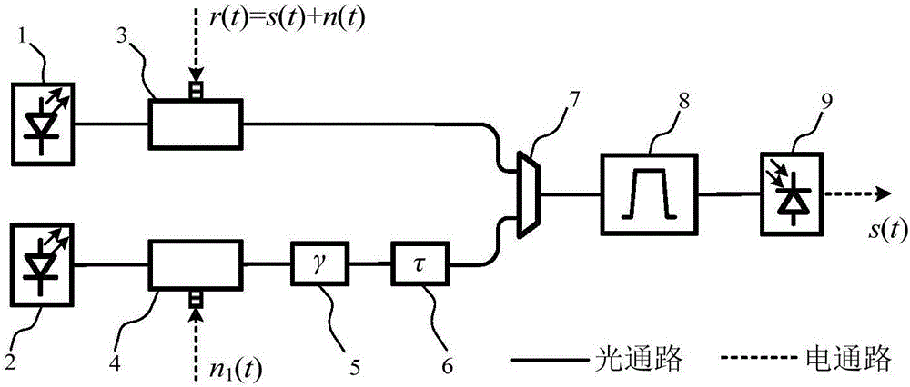
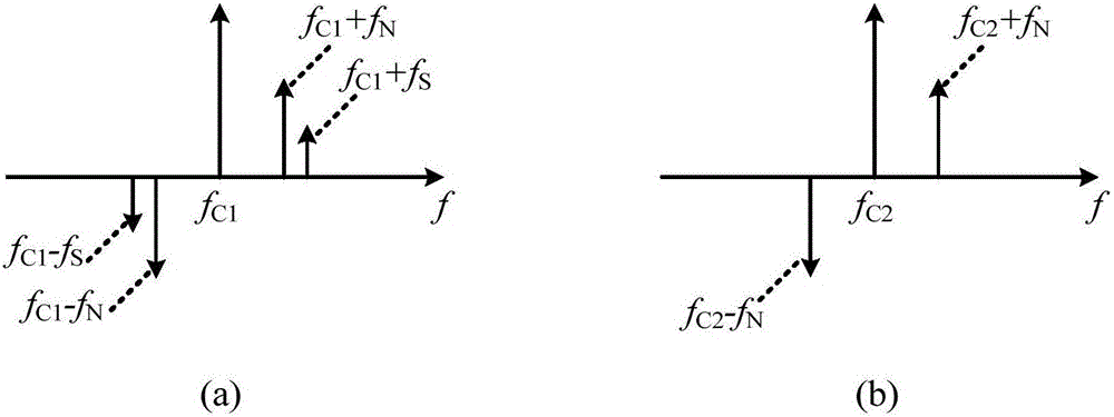
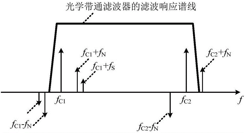
[0030] figure 1 It is a structural block diagram of the photonic microwave self-interference signal elimination device of the present invention. The signal received by the receiving antenna r(t)=s(t)+n(t) (s(t) is a useful signal, the frequency is f S ; n(t) is the interference signal, the frequency is f N ) is modulated by the first electro-optical phase modulator to the optical carrier output by the first laser (the frequency is f C1 ), the output spectrum is as figure 2 As shown in (a), the phases of the left and right bands are opposite (that is, the difference is π). Cancellation signal n induced by the transmitting antenna 1 (t) (with frequency f N ) is modulated by the second electro-optical phase modulator to the optical carrier output by the second laser (the frequency is f C2 ), the output spectrum is as figure 2 As shown in (b), the phases of the left and right bands are opposite (that is, the difference is π). The optical-carrying microwave signal is tran...


PUM


Abstract

The invention discloses a device and a method for eliminating photonic microwave self-interference signals, and belongs to the technical field of microwave photonics. According to the device disclosed by the invention, useful signals received of a receiving antenna, self-interference signals and cancellation signals led out by a transmitting antenna are modulated to an optical carrier outputted by a laser by adopting an electro-optic phase modulator, a left sideband and a right side band of phase modulation optical carrier microwave signals are opposite in phase, right sideband plus optical carrier signals and left sideband plus optical carrier signals are acquired through an optical band-pass filter, and the signals are converted through a photoelectric detector so as to eliminate interference signals. The device disclosed by the invention does not need to carry out DC bias voltage control on the electro-optic phase modulator, so that the system structure is greatly simplified, and the system stability is enhanced. Amplitude and time delay regulation and control in an optical domain are great in bandwidth and high in regulation precision, and restrictions of small bandwidth and low regulation precision of an electronic technology are overcome.

Description

technical field [0001] The invention belongs to the field of microwave photon technology, and in particular relates to a photon microwave self-interference signal elimination device and method. Background technique [0002] With the extensive development of wireless communication services, microwave spectrum resources are becoming increasingly scarce. Current wireless communication equipment mainly adopts frequency division duplex or time division duplex technology. Frequency-division duplex technology uses different carrier frequencies for communication when transmitting and receiving signals between systems at the same time; time-division duplex technology uses the same carrier frequency to transmit and receive signals at different times. Therefore, frequency division duplexing or time division duplexing is actually a half-duplex communication mode, which cannot effectively improve the utilization efficiency of spectrum resources. Full-duplex technology uses the same fre...

Claims


Application Information

Patent Timeline
IPC IPC(8): H04B10/69H04B10/61
CPCH04B10/6165H04B10/691
Inventor 韩秀友邵宇辰霍泊帆马亮谷一英赵明山
Owner DALIAN UNIV OF TECH
Why Eureka
Try Eureka