
Liquid crystal display panel

A technology of liquid crystal display panels and color film substrates, applied in nonlinear optics, instruments, optics, etc., can solve problems such as uneven display, panel deformation, and low box thickness, and achieve the effect of solving uneven display

Inactive Publication Date: 2020-04-17
WUHAN CHINA STAR OPTOELECTRONICS TECH CO LTD
View PDF3 Cites 4 Cited by
  • Summary
  • Abstract
  • Description
  • Claims
  • Application Information

AI Technical Summary

Problems solved by technology

The existing design will retain the liquid crystal layer in the light-transmitting area of ​​the blind hole, and the panel will be deformed under the action of stress. In the light-transmitting area of ​​the blind hole, due to lack of support, the thickness of the cell will be low and the display will be uneven. Causes problems with optical uniformity of display panels

Method used


Image

  • Liquid crystal display panel
  • Liquid crystal display panel
  • Liquid crystal display panel

Examples


Embodiment Construction

[0028] In order to make the object, technical solution and effect of the present invention more clear and definite, the present invention will be further described in detail below with reference to the accompanying drawings. It should be understood that the specific embodiments described here are only used to explain the present invention, and the word "embodiment" used in the description of the present invention is meant to be used as an example, illustration or illustration, and is not intended to limit the present invention.

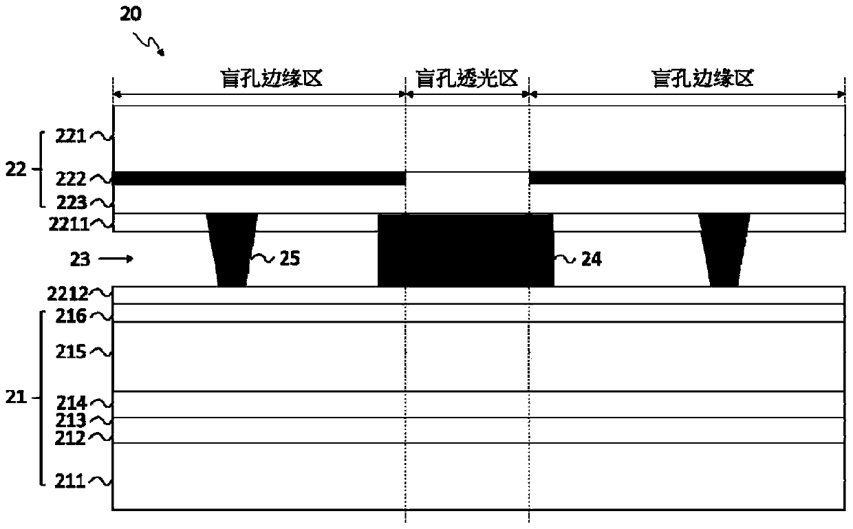
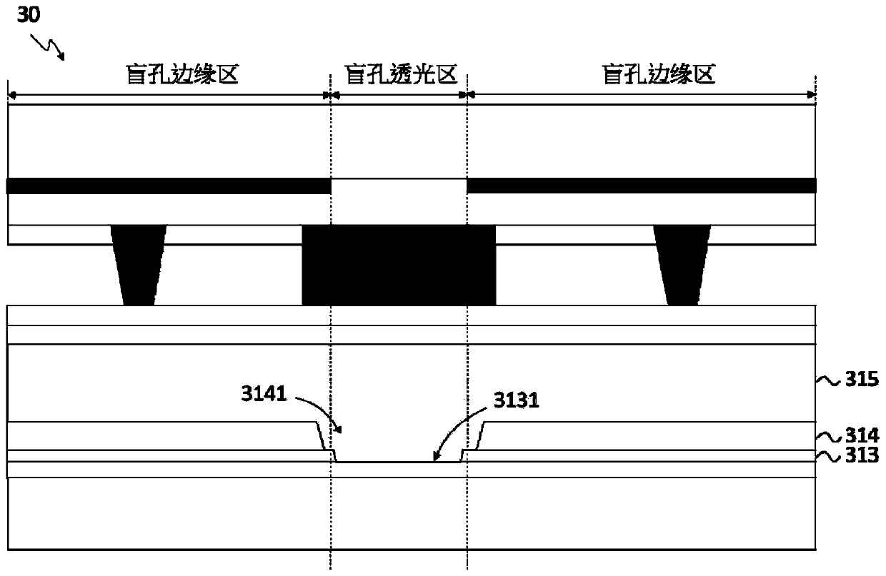
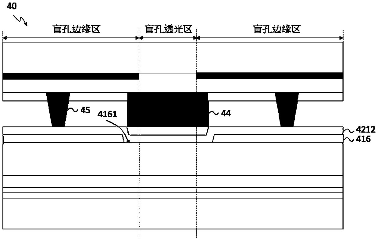
[0029] The invention provides a liquid crystal display panel, which has the effect of reducing the liquid crystal in the light-transmitting area of ​​the blind hole and improving the deformation between the substrates in the light-transmitting area of ​​the blind hole, so that the electronic equipment (such as an imaging device) installed in the light-transmitting area of ​​the blind hole is normal. function.

[0030] Please refer to figure 1 , figu...


PUM


Abstract

The invention provides a liquid crystal display panel. The panel comprises a blind hole region, the blind hole area comprises a blind hole light-transmitting area and a blind hole edge area arranged around the blind hole light-transmitting area. A first transparent support is arranged on the color film substrate in the blind hole light-transmitting area; the first transparent support is used for supporting the color film substrate and the thin film transistor array substrate which are positioned in the blind hole light transmission area; a black matrix is arranged on the color film substrate at the edge area of the blind hole, a plurality of second transparent supports are correspondingly arranged at the black matrix, and the problem of optical uniformity of the display panel can be improved through the first transparent supports located in the light-transmitting area of the blind hole.

Description

technical field [0001] The invention relates to the field of display technology, in particular to a liquid crystal display panel which improves the deformation between a color filter substrate and a thin film transistor array substrate. Background technique [0002] Since the development of smart terminal screens, the screen-to-body ratio has been able to reach a full-screen level of more than 90%. Based on the structural design of the full-screen, cameras, earpieces, sensors, etc. need to be installed on the panel by punching holes (such as blind holes). in the display area. The existing design will retain the liquid crystal layer in the light-transmitting area of ​​the blind hole, and the panel will be deformed under the action of stress. In the light-transmitting area of ​​the blind hole, due to the lack of support, the thickness of the cell will be low and the display will be uneven. This causes a problem of optical uniformity of the display panel. Therefore, it is nec...

Claims


Application Information

Patent Timeline
Patent Type & Authority Applications(China)
IPC IPC(8): G02F1/1339
CPCG02F1/13394G02F1/13396G02F1/13398
Inventor 熊兴唐维
Owner WUHAN CHINA STAR OPTOELECTRONICS TECH CO LTD
Learn More