

Hollow composite tire structure
A hollow and outer tire technology, applied in the direction of non-pneumatic tires, tire parts, transportation and packaging, etc., can solve the problems of poor shock absorption effect of solid tires, achieve the effect of improving heat dissipation, good shock absorption effect, and prolonging the service life
- Summary
- Abstract
- Description
- Claims
- Application Information
AI Technical Summary
Problems solved by technology
Method used
Image

Examples
Embodiment 1
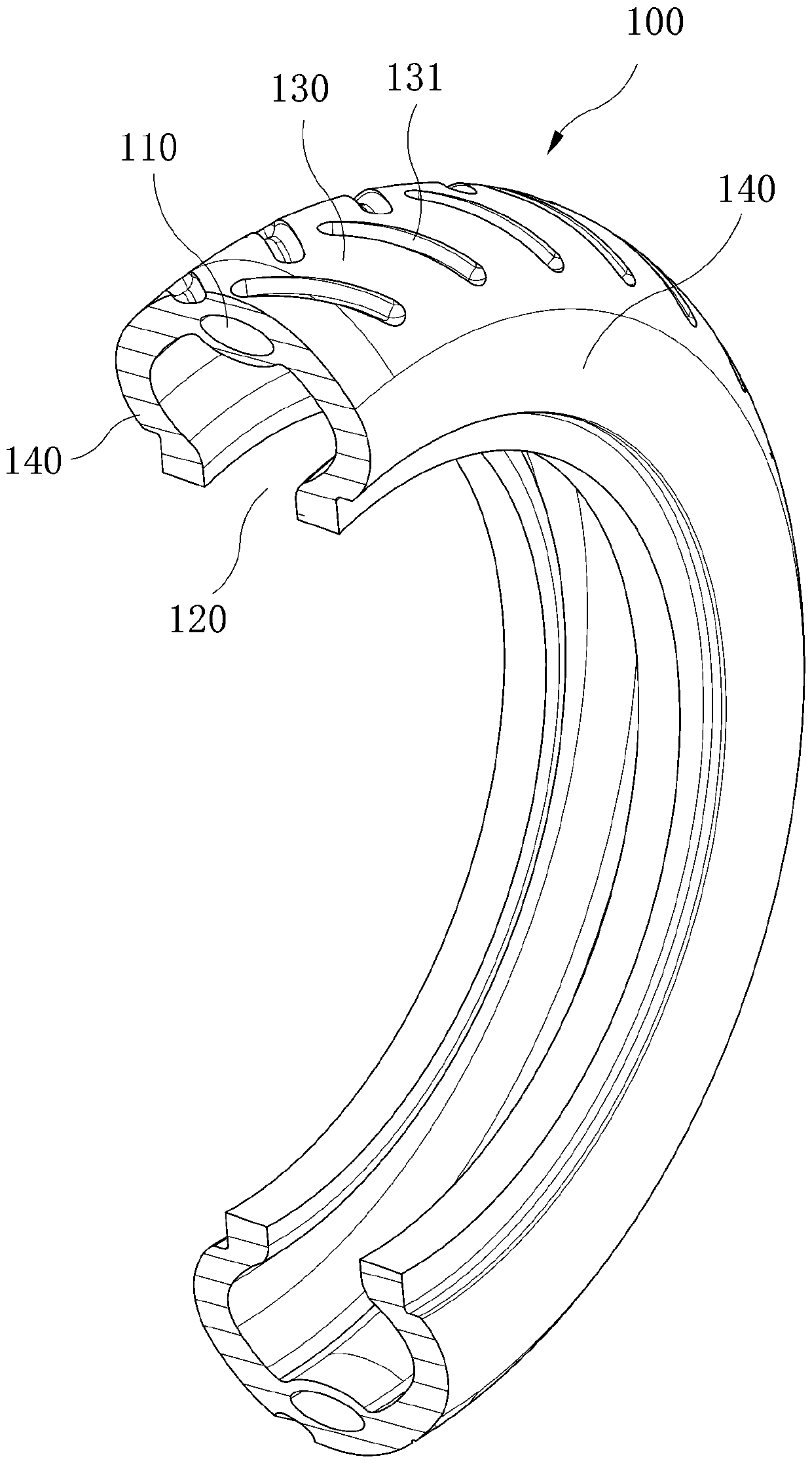
[0028] Such as figure 1 As shown, the hollow composite tire structure of the present embodiment includes a tire cover 100, wherein the cover tire 100 is provided with a first chamber 110 and a second chamber 120, and the first chamber 110 is a sealed chamber, which is arranged along the tire cover 100. The circumferential arrangement; the second chamber 120 is also arranged along the circumferential direction of the tire 100, which has an opening facing inward.
[0029] In this embodiment, the first chamber 110 and the second chamber 120 are provided on the tire 100 so that the tire 100 has a larger deformation space, so as to achieve a good shock absorption effect.
[0030] The tire casing 100 includes a tread 130 and sidewalls 140 connected to both ends of the tread 130 . In order to improve the antiskid performance of the tire 100 , grooves 131 can be provided on the tread 130 of the tire 100 .
Embodiment 2
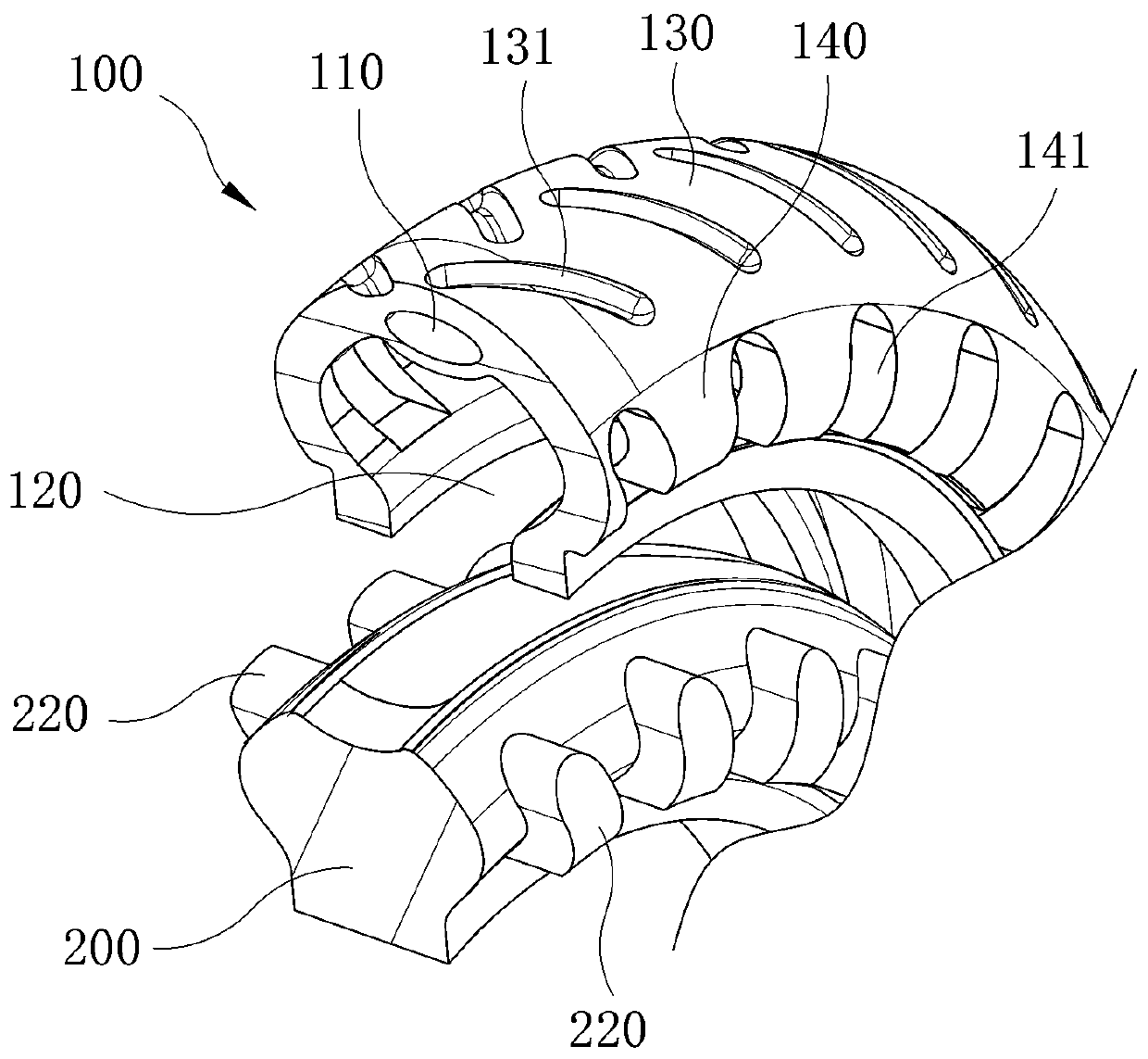
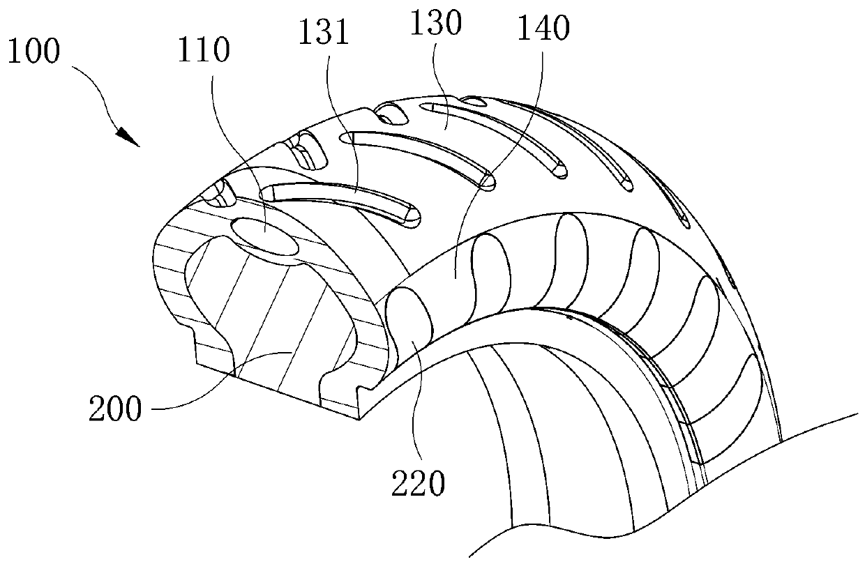
[0032] Such as figure 2 and image 3 As shown, this embodiment is further improved on the basis of the first embodiment above, specifically, an inner tube 200 is arranged in the second chamber 120 of the outer tire 100, and the inner tube 200 is a solid structure.
[0033] In this embodiment, the arrangement of the inner tube 200 can enhance the support strength of the hollow composite tire, so that the hollow composite tire can have the beneficial effects of good shock absorption effect and good support strength.
[0034] In order to enhance the stability of the connection between the tire 100 and the inner tube 200 , the sidewall 140 is provided with a locking groove 141 , and correspondingly, the inner tire 200 is provided with a boss 220 engaged with the locking groove 141 .
[0035] The inner tube 200 and the outer tire 100 of the hollow composite tire can be made of the same material or different materials, wherein the hardness of the inner tube 200 is greater than tha...
Embodiment 3
[0037] Such as Figure 4 and Figure 5 As shown, this embodiment improves the above-mentioned second embodiment. The difference from the second embodiment is that the inner tube 200 is not a solid tire, but a third chamber 210 is set on the inner tube 200. The third The chamber 210 is arranged along the radial direction of the inner tube 200 . And the third chamber 210 has an opening away from the tire casing 100 .
[0038] Compared with the second embodiment, this embodiment can further improve the shock absorption effect by setting the third chamber 210, and also improve the heat dissipation of the inner tube 200, so that the performance of the inner tube 200 is better; and, with the first chamber 110, it can The bouncing problem caused by the third chamber 210 is avoided.
[0039] The above-mentioned first chamber 110 may be provided in one or in multiples.
[0040] To sum up, the key of the present invention is that the present invention forms the first chamber 110 and...
PUM
 Abstract
Description
Claims
Application Information