Paper sheet stacking apparatus and image forming system
A paper and image technology, applied in the field of paper stacking devices and image forming systems, can solve problems such as poor downtime and achieve the effect of suppressing downtime
- Summary
- Abstract
- Description
- Claims
- Application Information
AI Technical Summary
Problems solved by technology
Method used
Image
Examples
no. 1 approach
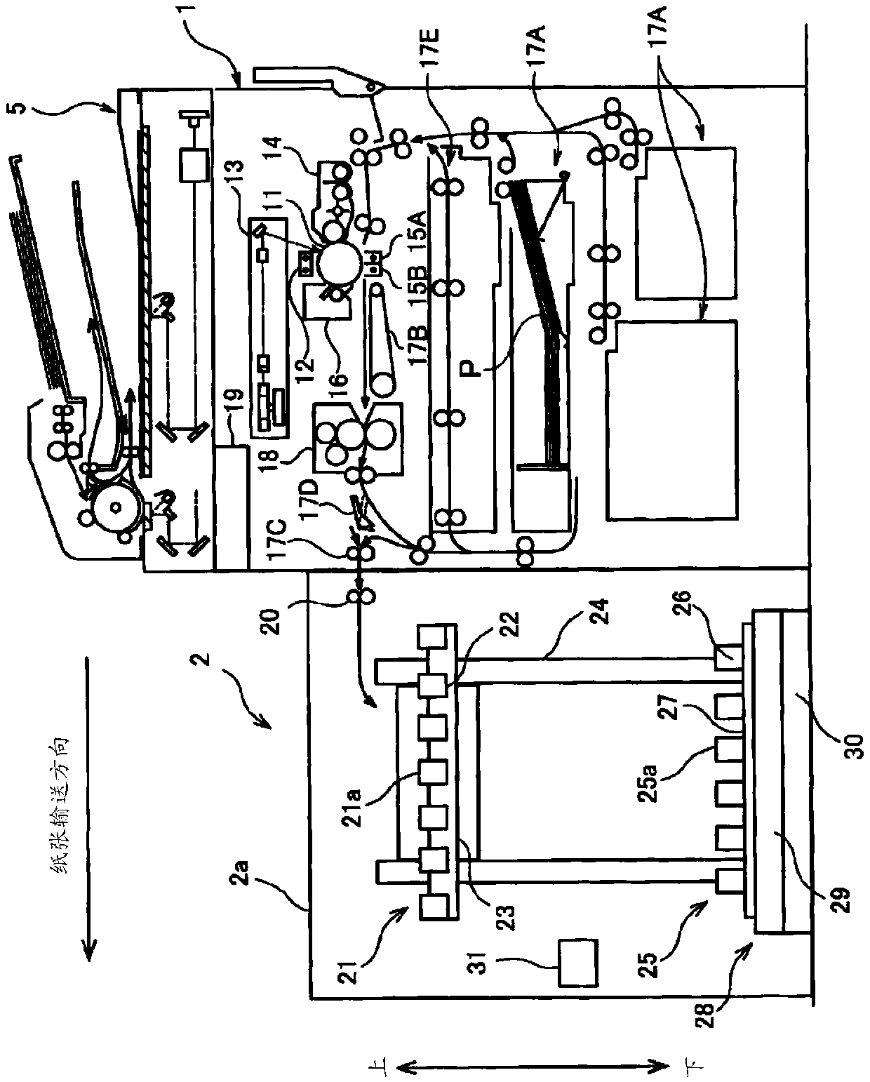
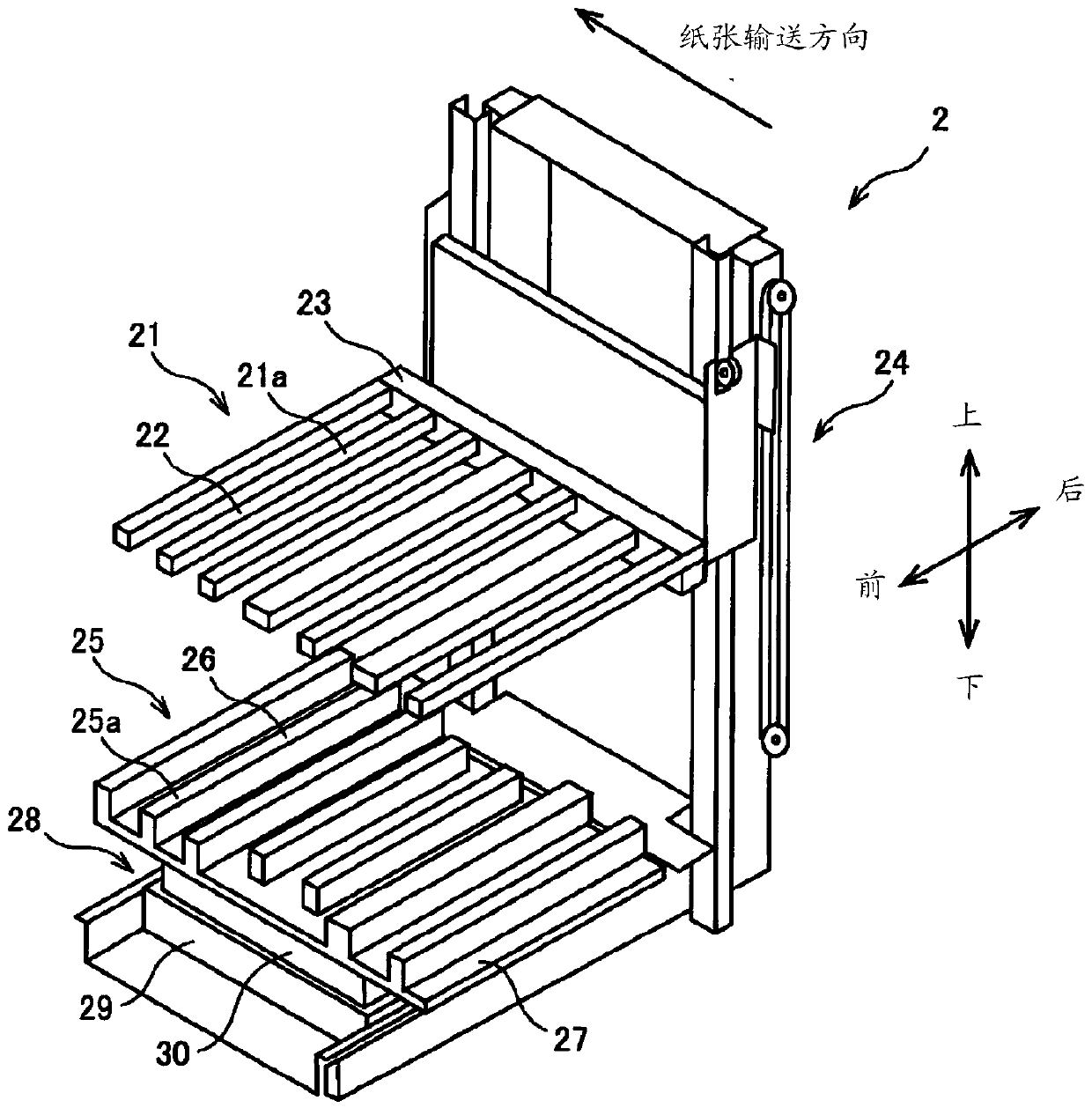
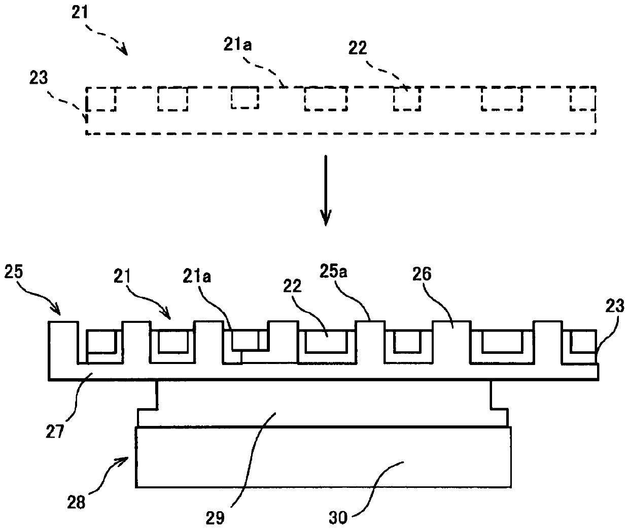
[0066] figure 1 It is a front view schematically showing the structure of the image forming system of this embodiment. The image forming system of this embodiment has an image forming apparatus 1 and a paper stacking apparatus 2.
[0067] The image forming apparatus 1 is an electrophotographic image forming apparatus such as a copier, and forms an image on a paper P based on image data. The image forming apparatus 1 has a document reading device 5, a photoreceptor 11, a charging unit 12, an image exposure unit 13, a developing unit 14, a transfer unit 15A, a separation unit 15B, a cleaning device 16, a fixing device 18, and an image formation control unit 19. .
[0068] The document reading device 5 has an automatic document conveying unit which is arranged on the upper part of the housing of the image forming apparatus 1 and automatically moves the document when reading an image. The document reading device 5 reads an image formed on a document, and outputs a predetermined image...
no. 2 approach
[0112] Hereinafter, the image forming system of the second embodiment will be described. The image forming system of the second embodiment is different from the first embodiment in the structure of the sheet stacking device 2. The description of the content overlapping with the first embodiment will be omitted, and the description will focus on the difference below.
[0113] Image 6 It is an explanatory diagram showing the structure of the sheet stacking device 2 of the second embodiment. The paper stacking device 2 is a paper discharge section 20 (in Image 6 Omitted), the first pallet 21, the lifting device 24, the second pallet 25, the transport vehicle 40, and the stacking control unit 31 are mainly constituted. The structures of the paper ejection unit 20, the first tray 21, the lifting device 24, and the stack control unit 31 are the same as those of the first embodiment.
[0114] In this embodiment, the second tray 25 is mounted on the transport vehicle 40 housed in the d...
no. 3 approach
[0122] Hereinafter, the image forming system of the third embodiment will be described. The image forming system of the third embodiment is different from the first embodiment in the structure of the sheet stacking device 2. The description of the content overlapping with the first embodiment will be omitted below, and the description will focus on the difference below.
[0123] Figure 8 It is an explanatory diagram showing the structure of the sheet stacking device 2 of the third embodiment. The paper stacking device 2 is a paper discharge section 20 (in Figure 8 Omitted), the first tray 21, the lifting device 24, the plurality of second trays 25, the front and rear driving device 28, and the stacking control unit 31 are constituted by the main body. The structure of the paper discharge unit 20, the first tray 21, the lifting device 24, the front-rear driving device 28, and the stack control unit 31 is the same as that of the first embodiment.
[0124] In the present embodimen...
PUM
 Abstract
Description
Claims
Application Information
 - R&D
- Intellectual Property
- Life Sciences
- Materials
- Tech Scout
- Unparalleled Data Quality
- Higher Quality Content
- 60% Fewer Hallucinations
Browse by: Latest US Patents, China's latest patents, Technical Efficacy Thesaurus, Application Domain, Technology Topic, Popular Technical Reports.
© 2025 PatSnap. All rights reserved.Legal|Privacy policy|Modern Slavery Act Transparency Statement|Sitemap|About US| Contact US: help@patsnap.com


