Cable laying device for power supply company

A technology of cable laying and power supply companies, which is applied in the direction of cable installation, cable laying equipment, and cable installation in tunnels. It can solve the problems of difficult cable laying, high labor intensity, and low cable laying efficiency, so as to save manpower and material resources. , Convenient and fast operation, and the effect of improving the efficiency of cable laying construction

Active Publication Date: 2020-04-24
STATE GRID CORP OF CHINA +1
View PDF5 Cites 26 Cited by
  • Summary
  • Abstract
  • Description
  • Claims
  • Application Information

AI Technical Summary

Problems solved by technology

At present, the cables are generally placed on the brackets manually. When the height of the bracket is high, the operator needs to build a scaffold in the tunnel first, and then use the hoist to pull the cable to a suitable height, and then move the cable to the bracket. When the bracket is low Many people are required to manually place the cables on the brackets, which is labor intensive and the cable laying efficiency is low. If the cables to be laid are long, the labor cost is higher and the cable laying is more difficult

Method used


Image

  • Cable laying device for power supply company
  • Cable laying device for power supply company
  • Cable laying device for power supply company

Examples


Embodiment Construction

[0023] The following will clearly and completely describe the technical solutions in the embodiments of the present invention with reference to the accompanying drawings in the embodiments of the present invention. Obviously, the described embodiments are only some, not all, embodiments of the present invention. Based on the embodiments of the present invention, all other embodiments obtained by persons of ordinary skill in the art without making creative efforts belong to the protection scope of the present invention.

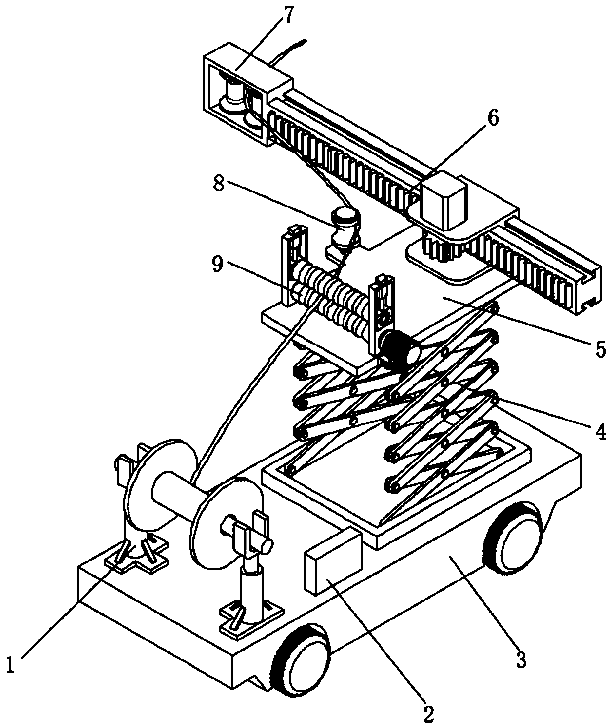
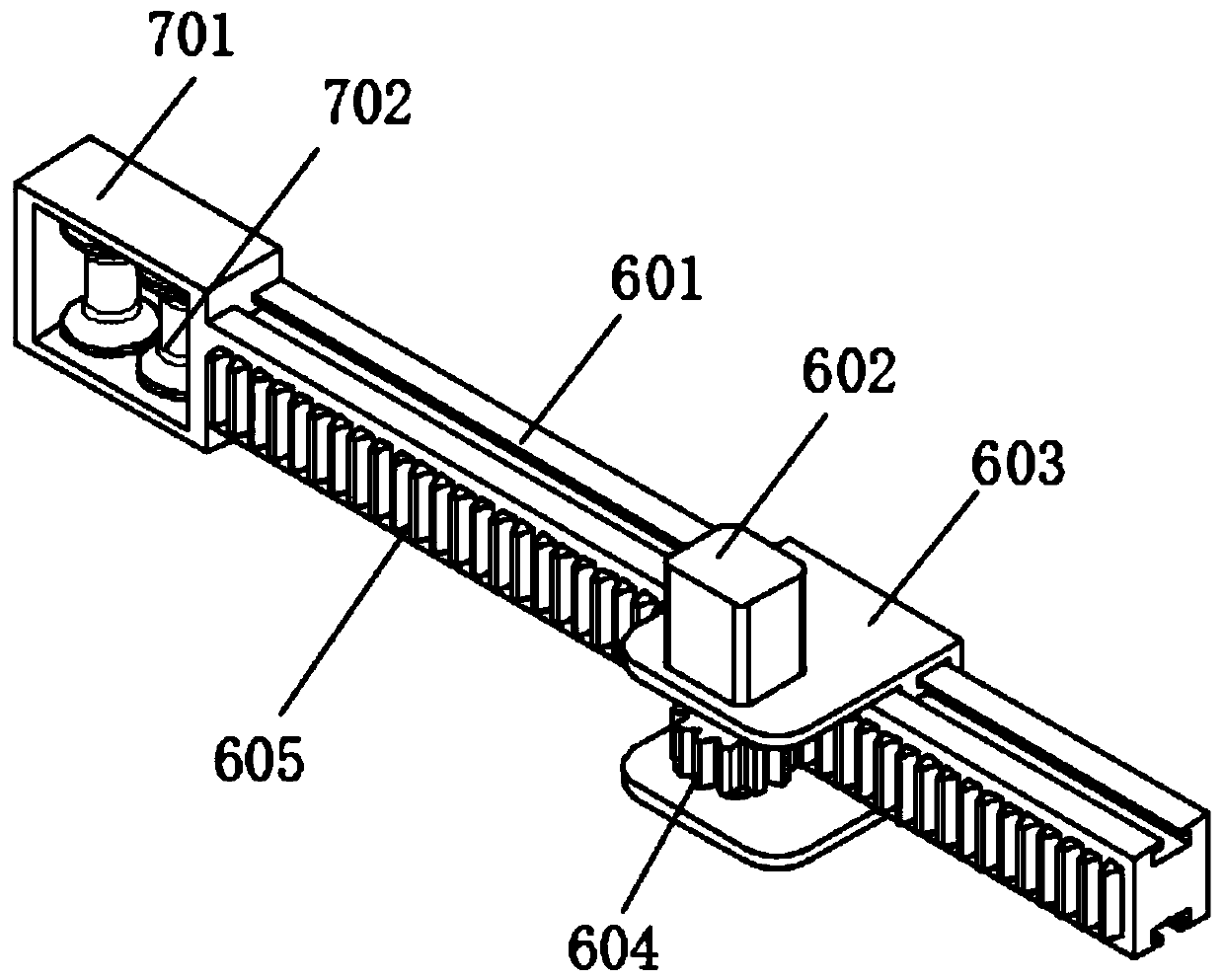
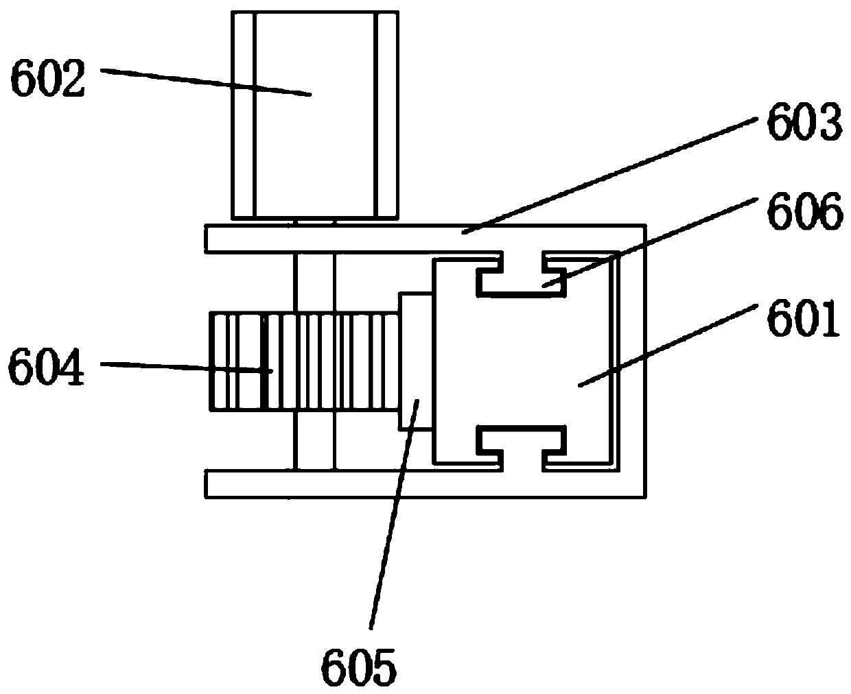
[0024] see Figure 1-5 , the present invention provides a technical solution: a cable laying device for a power supply company, including a trolley 3, a support device 1 for supporting cables is provided on one side of the table of the trolley 3, and the support device 1 is located in the running direction of the trolley 3 The front end of the supporting device 1 includes two groups of symmetrically arranged hydraulic cylinders, the fixed end of each group of ...


PUM


Abstract

The invention discloses a cable laying device for a power supply company. The device comprises a walking trolley. A supporting device used for supporting a cable is arranged on one side of the table top of the walking trolley and located at the front end of the running direction of the walking trolley. A lifting driving mechanism is arranged on the other side of the table top of the walking trolley. A workbench is arranged at the upper end of the lifting driving mechanism, and the lifting driving mechanism can drive the workbench to move up and down. A conveying mechanism used for lifting andpulling the cable to move is arranged on one side of the table top of the workbench and located at the front end of the operation direction of the workbench. A telescopic mechanism perpendicular to the operation direction of the walking trolley is arranged on the other side of the table top of the workbench, and a first roller assembly assisting the cable in moving is arranged at the tail end of the telescopic mechanism. According to the invention, the device can automatically lay cables of different specifications on a tunnel support; the operation is convenient and fast, and manpower and material resources are saved; different working conditions are adapted; and the cable laying construction efficiency is improved.

Description

technical field [0001] The invention relates to the technical field of cable laying equipment, in particular to a cable laying device for a power supply company. Background technique [0002] In the cable tunnel laying project, the cable needs to be placed on the support when laying the cable. There are multi-layer supports inside the cable tunnel, and the support heights are different. At present, the cables are generally placed on the brackets manually. When the height of the bracket is high, the operator needs to build a scaffold in the tunnel first, and then use the hoist to pull the cable to a suitable height, and then move the cable to the bracket. When the bracket is low Many people are required to manually place the cables on the brackets, which is labor-intensive and the cable laying efficiency is low. If the cables to be laid are long, the labor cost is higher and the cable laying is more difficult. Contents of the invention [0003] The technical problem to be ...

Claims


Application Information

Patent Timeline
Patent Type & Authority Applications(China)
IPC IPC(8): H02G1/06H02G9/08
CPCH02G1/06H02G9/08
Inventor 南钰赵鑫李翔宋丽华王磊张珂
Owner STATE GRID CORP OF CHINA
Why Eureka
Try Eureka