Design method and production method of orthodontic brace

A design method and device technology, applied in the field of medical devices, can solve problems such as airway obstruction, user discomfort, and large oral damage, and achieve the effects of personalized preparation, comfortable wearing, and convenient removal and wearing

Active Publication Date: 2020-04-28
SHANGHAI SMARTEE DENTI TECH CO LTD +2
View PDF3 Cites 5 Cited by
  • Summary
  • Abstract
  • Description
  • Claims
  • Application Information

AI Technical Summary

Problems solved by technology

[0003] However, most of the above treatment methods are fixed treatment methods, which not only cause great damage to the user's oral cavity, but also make the user's experience and comfort poor.
In addition, during the operation of the above correction process, it is necessary for the user to insert the wrench into the small hole of the intraoral device to perform the bow expansion operation, which greatly increases the inconvenience of the user's bow expansion, and it is also easy for the small wrench to fall into the mouth during operation. Risk

Method used


Image

  • Design method and production method of orthodontic brace
  • Design method and production method of orthodontic brace
  • Design method and production method of orthodontic brace

Examples


Embodiment 1

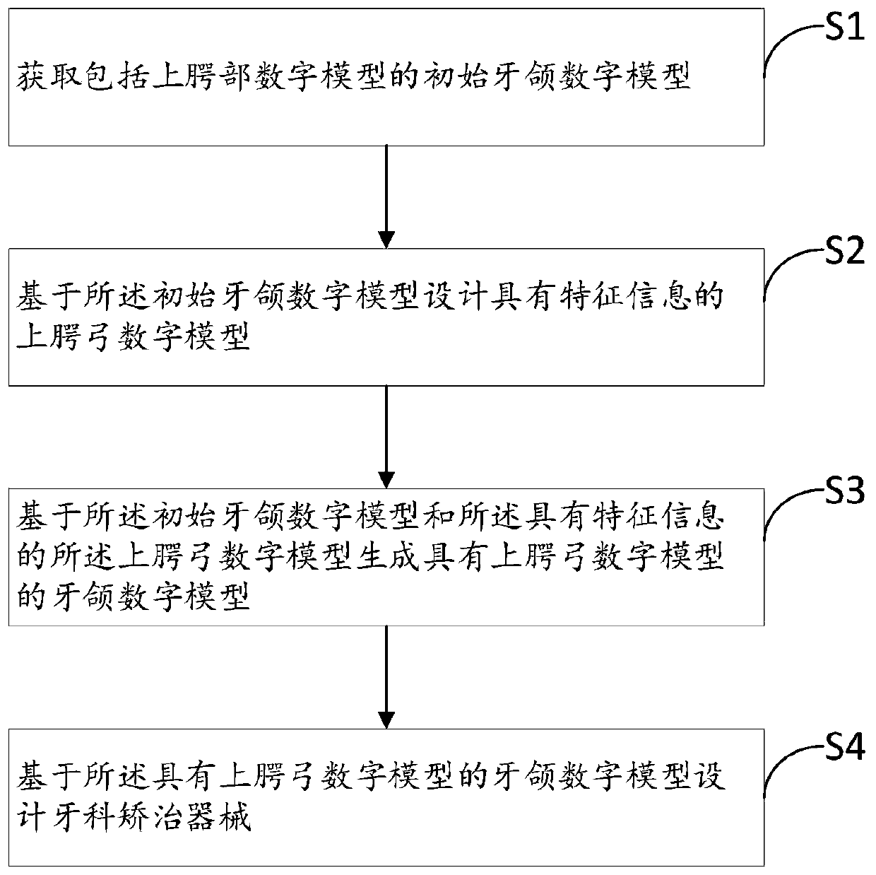
[0057] In the step S1 of Embodiment 1 of the present invention, an intraoral scan is performed on the user, and the scanning range covers the upper jaw and upper dental arch of the user, so as to obtain the initial dental and jaw digital model including the digital model of the upper palate .

[0058] In some embodiments of the present invention, a medical silicone material is used to take an impression in the user's mouth to obtain a physical impression model, and the physical impression model includes a palate impression and a maxillary impression; the physical impression model is converted into After the physical male model is scanned, the physical male model is scanned to obtain the initial dental and jaw digital model including the upper palate digital model.

[0059] In the step S2 of Embodiment 1 of the present invention, the feature information includes size information and preset position information of the digital model of the palatal arch. The preset position infor...

Embodiment 2

[0083] The difference between the design method provided by Embodiment 2 of the present invention and the design method provided by Embodiment 1 is that: the palatal arch is provided with a reinforcing part that enhances the expansion or contraction of the palatal arch. The reinforcing part is at least one reinforcing ridge provided on the palate arch and consistent with or different from the curvature of the palate. The cross-section of the reinforcing ridge along the sagittal plane near-distal direction is a discontinuous cross-section or a continuous cross-section. When it is a continuous cross-section, the reinforcing ridge can generate sufficient force to achieve the effect of expanding or retracting the bow.

[0084] Figure 4 It is a schematic structural view of the second dental appliance obtained through the design method and preparation method of embodiment 2 of the present invention.

[0085] refer to Figure 2a and Figure 4 The main difference between the secon...

Embodiment 3

[0102] In Embodiment 3 of the present invention, the cross-section in the near-distal direction of the cross-section of the reinforcing ridge is designed to be arranged below the cross-section of the palatine arch. More specifically, the reinforcing ridge is provided along the lower side of the upper palatal arch cross-section, and is only provided on the lower side.

[0103] Figure 5b It is a schematic diagram of the cross-section of the structure composed of three arc-shaped reinforcing ridges and the first palatal arch obtained through the design method and preparation method of Example 3 along the mesial-distal direction.

[0104] refer to Figure 5b , the design of the fourth arc-shaped reinforcing ridge 41, the fifth arc-shaped reinforcing ridge 42 and the sixth arc-shaped reinforcing ridge 43 along the buccal-lingual direction are respectively the same as those of the first arc-shaped reinforcing ridge 31 and the first arc-shaped reinforcing ridge 31 described in Embo...


PUM


Abstract

The invention provides a design method of an orthodontic brace. The design method of the orthodontic brace comprises the following steps: acquiring an initial digital dental model; designing a digitalupper palatal arch model with characteristic information; and generating a digital dental model with the digital upper palatal arch model, and designing the orthodontic brace. The characteristic information comprises size information of the digital upper palatal arch model and preset position information, and the preset position information of an upper palatal arch is that two ends of the upper palatal arch are arranged in positions of lingual gingiva margins in a backteeth area of the initial digital dental model or positions, close to the gingival margins, on lingual sides in the backteetharea of the initial digital dental model so that when the orthodontic brace acts on teeth, the upper palatal arch can induce buccolingual lateral amplification of maxillary palatal suture bone deposition through deformation, and the teeth in the backteeth area conduct buccolingual lateral movements under the action of the orthodontic brace. A production method of the orthodontic brace is further provided.

Description

technical field [0001] The invention relates to the technical field of medical devices, in particular to a design method and a preparation method of a dental orthodontic device. Background technique [0002] Among orthodontists, crowding is a common clinical manifestation, although the current commonly used orthodontic design is tooth extraction, proximal surface deglazing, pushing molars to distal or labially tilting teeth to provide space. But there are still some users, the crowding is mainly manifested as insufficient dental arch width, and the crowding will be improved after the dental arch width is opened. Bow expansion treatment is a common treatment method for dental arch width adjustment. Common expansion methods include fixed expansion device expansion, four-eye spring expansion, knight expansion, implant-assisted expansion, surgical operation-assisted expansion, etc. . Invisible aligners also have a certain ability to expand the arch. Previous studies have shown...

Claims


Application Information

Patent Timeline
IPC IPC(8): A61C7/00
CPCA61C7/002
Inventor 沈刚魏亭亭王特蒋健羽徐子卿郭涛王星星杨森森庄慧敏吴刚
Owner SHANGHAI SMARTEE DENTI TECH CO LTD
Why Eureka
Try Eureka