
Film cutting machine

A cutting machine and film technology, which is applied in metal processing and other directions, can solve the problems of high labor intensity for operators, time-consuming and labor-intensive cutting of waste edges, and impact on production efficiency, so as to achieve good cutting effect and improve cutting efficiency , the effect of a reasonable structure

Inactive Publication Date: 2020-04-28
SHANDONG PHARMA GLASS
View PDF0 Cites 0 Cited by
  • Summary
  • Abstract
  • Description
  • Claims
  • Application Information

AI Technical Summary

Problems solved by technology

Molding is used for vulcanization, so each mold product is a whole mold product after vulcanization. The operator needs to cut off a circle of waste edges and then cut it into three pieces. Cut into three small pieces with scissors, and each small piece is punched into a single rubber plug with the punching die (the punching die requires high precision, so it should not be too large). production efficiency
In particular, cutting waste edges is time-consuming and labor-intensive, and it is easy to make cutting errors, resulting in the scrapping of the entire mold

Method used


Image

  • Film cutting machine
  • Film cutting machine

Examples


Embodiment Construction

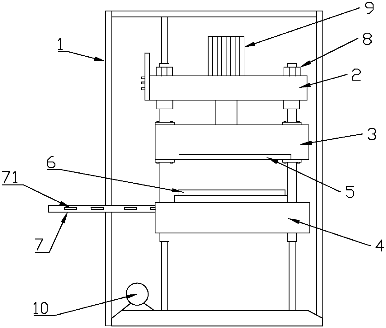
[0018] Such as Figure 1-Figure 2 The film cutting machine shown is characterized by comprising a support 1, a power fixing frame 2, a cutting structure and a finishing mechanism;

[0019] The power fixing frame 2 is fixed side by side with three power mechanisms; the main hydraulic cylinder 9 in the middle and the auxiliary hydraulic cylinders 8 distributed on the left and right sides of the power fixing frame. The three are matched with each other evenly and the cutting effect is better.

[0020] The cutting mechanism includes a cutting die and upper and lower cutters. The upper cutter 5 is fixed on the upper knife holder 3, the lower cutter 6 is fixed on the lower knife holder 4, and the cutting die is fixed on the lower knife holder 4. The upper cutting knife and the lower cutting knife are set up around the cutting die; the shape of the cutting die matches the shape of the whole mold.

[0021] The bottom of the cutting die is provided with a supporting oil cylinder, which can m...


PUM


Abstract

The invention relates to a film cutting machine. The film cutting machine includes a support, a power fixing frame, a cutting structure and an organizing mechanism. The power fixing frame is fixedly provided with three power mechanisms side by side. The cutting mechanism includes a cutting mould, an upper cutting knife and a lower cutting knife. The upper cutting knife is fixed on an upper knife rest, and the lower cutting knife is fixed on a lower knife rest. The cutting mould is fixed on the lower knife rest. The upper and lower cutting knives are set around the cutting mould. The film cutting machine has reasonable structure and smooth operation. Cutting is more powerful through a stable power mechanism, the cutting effect is good, and a feeding frame and the cutting mould are adopted in a cooperated mode to further improve cutting efficiency.

Description

Technical field [0001] The invention relates to a film cutting machine. Background technique [0002] At present, in the production of pharmaceutical halogenated butyl rubber stoppers, after the vulcanization process is completed, it needs to be transferred to the next process for punching. Compression molding is used during vulcanization, so each mold product is a complete mold product after vulcanization is completed. The operator needs to cut off a circle of waste edges and then cut into three pieces. The three pieces of product are required before punching in the subsequent process. Use scissors to cut into three small pieces, and each small piece is punched into a single rubber stopper in cooperation with the punching die (the punching die requires high precision, so it should not be too large). During the vulcanization and edge removal process, the operators are labor-intensive and affect normal Production efficiency. In particular, cutting waste edges is time-consuming a...

Claims


Application Information

Patent Timeline
Patent Type & Authority Applications(China)
IPC IPC(8): B26F1/40B26D7/06B26D7/18
CPCB26D7/0608B26D7/1863B26F1/40
Inventor 杨宏宁徐洪华齐元波
Owner SHANDONG PHARMA GLASS
Learn More