Supercharge Your Innovation With Domain-Expert AI Agents!

Marking detection equipment

A detection equipment and light detection technology, which is applied in electromagnetic radiation induction, printing, instruments, etc., can solve the problems of low code reading efficiency and achieve the effect of improving code reading efficiency and production efficiency

Active Publication Date: 2020-04-28
ZHUHAI GREE INTELLIGENT EQUIP CO LTD +1
View PDF8 Cites 1 Cited by
  • Summary
  • Abstract
  • Description
  • Claims
  • Application Information

AI Technical Summary

Problems solved by technology

[0004] The main purpose of the present invention is to provide a marking detection device to solve the problem of low code reading efficiency of the marking detection device in the prior art

Method used


Image

  • Marking detection equipment
  • Marking detection equipment
  • Marking detection equipment

Examples


Embodiment Construction

[0024] The following will clearly and completely describe the technical solutions in the embodiments of the present invention with reference to the accompanying drawings in the embodiments of the present invention. Obviously, the described embodiments are only some, not all, embodiments of the present invention. The following description of at least one exemplary embodiment is merely illustrative in nature and in no way taken as limiting the invention, its application or uses. Based on the embodiments of the present invention, all other embodiments obtained by persons of ordinary skill in the art without creative efforts fall within the protection scope of the present invention.

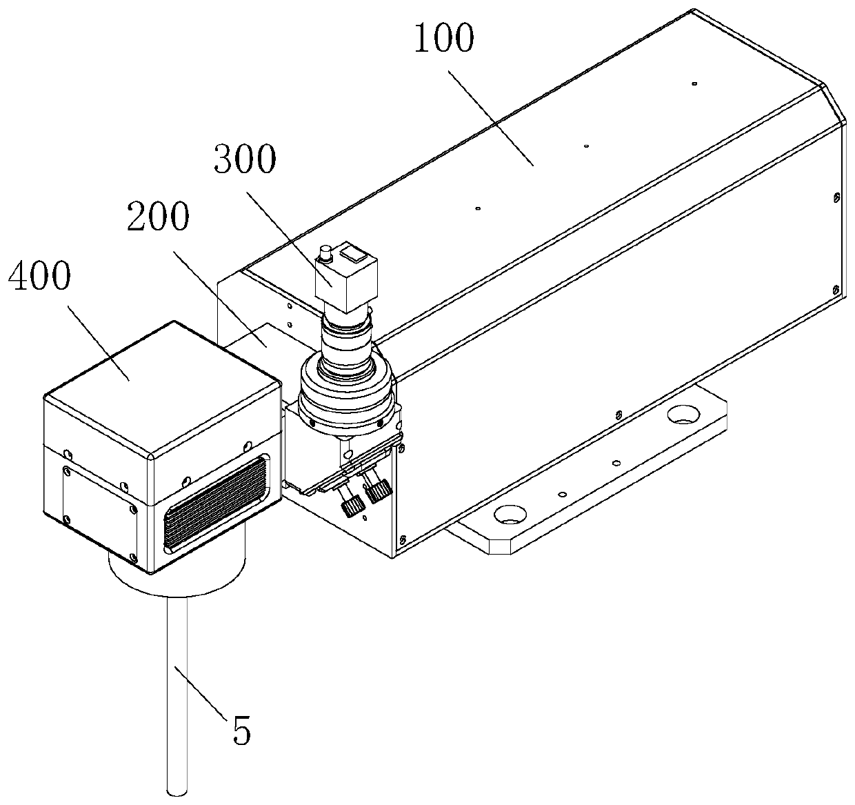
[0025] In order to solve the problem of low code reading efficiency of the marking detection equipment in the prior art, the present invention provides a marking detection equipment.

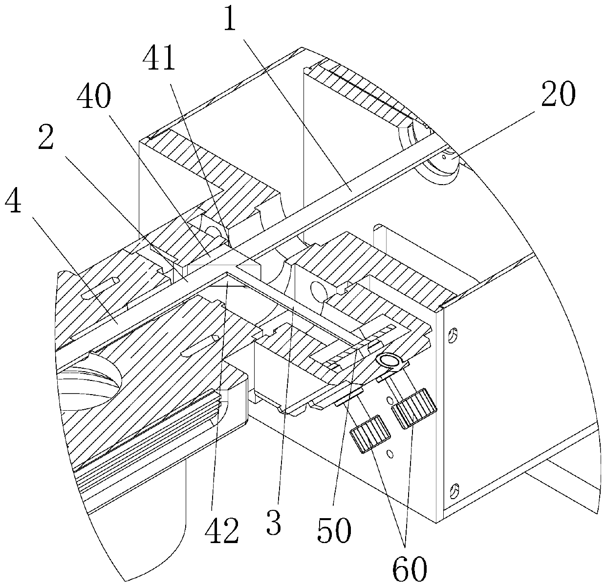
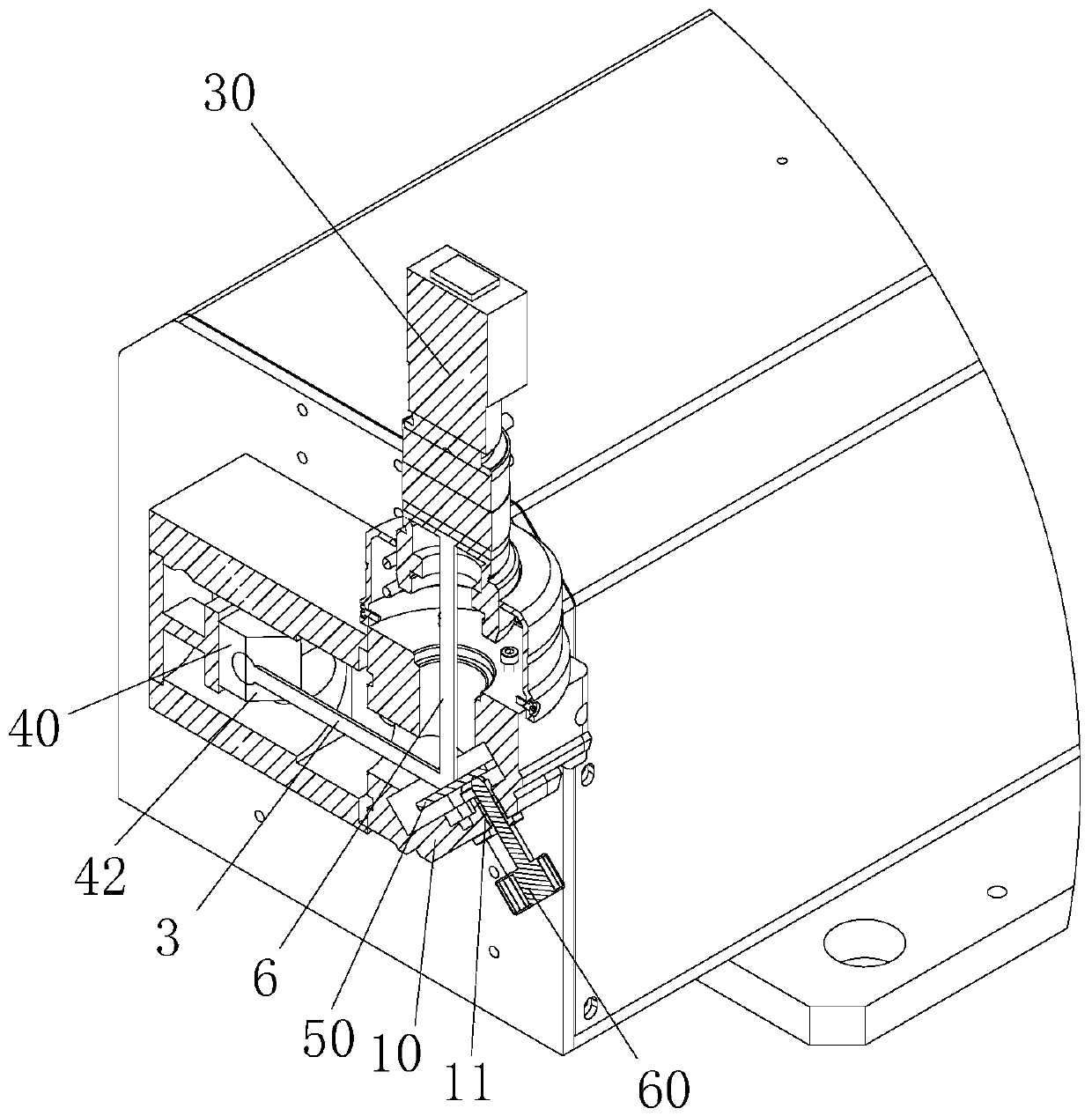
[0026] like Figure 1 to Figure 5 As shown, the marking detection device includes a housing 10, a transmitting modu...


PUM


Abstract

The invention provides marking detection equipment. The marking detection equipment comprises a shell, an emitting module and a detection module, wherein the emitting module is used for emitting a laser beam so as to mark an identification code on a workpiece through the laser beam; the detection module is used for acquiring a detection light reflected by the workpiece so as to carry out code reading detection on the identification code; the shell is provided with a first light path, a second light path and a third light path, the first end of the first light path communicates with the emitting module, the first end of the second light path communicates with the second end of the first light path, the first end of the third light path communicates with the first end of the second light path, and the second end of the third light path communicates with the detection module; when the marking detection equipment is in a marking mode, the laser beam emitted by the emitting module is focused on the workpiece through the first light path and the second light path; and when the marking detection equipment is in the detection mode, the detection light reflected by the workpiece enters thedetection module through the second light path and the third light path. According to the marking detection equipment, the problem of low code reading efficiency of marking detection equipment in theprior art is solved.

Description

technical field [0001] The invention relates to the technical field of laser marking, in particular to a marking detection device. Background technique [0002] With the development of industrial information technology, many industrial products use laser marking devices to mark the identification code on the specific position of the workpiece. After the marking is completed, the two-dimensional code on the workpiece needs to be checked by the code reading device. [0003] In the related art, the laser marking device and the code reading device of the marking detection equipment are respectively arranged at two positions. After the workpiece is marked at the laser marking device, the workpiece needs to be moved to the code reading device for code reading inspection. The time required to move the workpiece results in less efficient code reading, which results in less efficient workpiece production. Contents of the invention [0004] The main purpose of the present invention...

Claims


Application Information

Patent Timeline
Patent Type & Authority Applications(China)
IPC IPC(8): B41J2/475G06K7/10
CPCB41J2/475G06K7/10722
Inventor 周冠鸿陈兴华莫玉麟刘世基张力夫梁嘉祥詹高城刘诗雨
Owner ZHUHAI GREE INTELLIGENT EQUIP CO LTD
Features
  • R&D
  • Intellectual Property
  • Life Sciences
  • Materials
  • Tech Scout
  • Unparalleled Data Quality
  • Higher Quality Content
  • 60% Fewer Hallucinations
Learn More