Siro spinning fiber removing device

A technology of siro spinning, plied yarn, applied in spinning machine, textile and paper making, continuous winding spinning machine, etc., can solve the problems of eliminating hairiness, losing reuniting effect, losing siro spun yarn style, etc. , to achieve the effect of reducing the amount of hairiness

Active Publication Date: 2020-04-28
WUHAN TEXTILE UNIV
View PDF8 Cites 2 Cited by
  • Summary
  • Abstract
  • Description
  • Claims
  • Application Information

AI Technical Summary

Problems solved by technology

If the distance between the two yarns at the front nip is reduced, trying to make the double yarns enter the single-groove re-gathering groove will cause the Siro spinning to lose its unique strand style
In addition, during siro spinning, when two yarns pass through the converging point, they are combined into one yarn. At this time, the yarn is then introduced into the single-groove re-gathering groove. Since the two single yarns have been twisted and coiled together Together, the single groove refocusing grooves will also lose the refocusing effect and thus fail to eliminate hairiness to the greatest extent

Method used


Image

  • Siro spinning fiber removing device
  • Siro spinning fiber removing device
  • Siro spinning fiber removing device

Examples


Embodiment 1

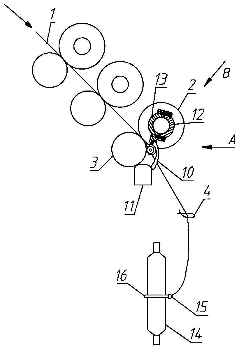
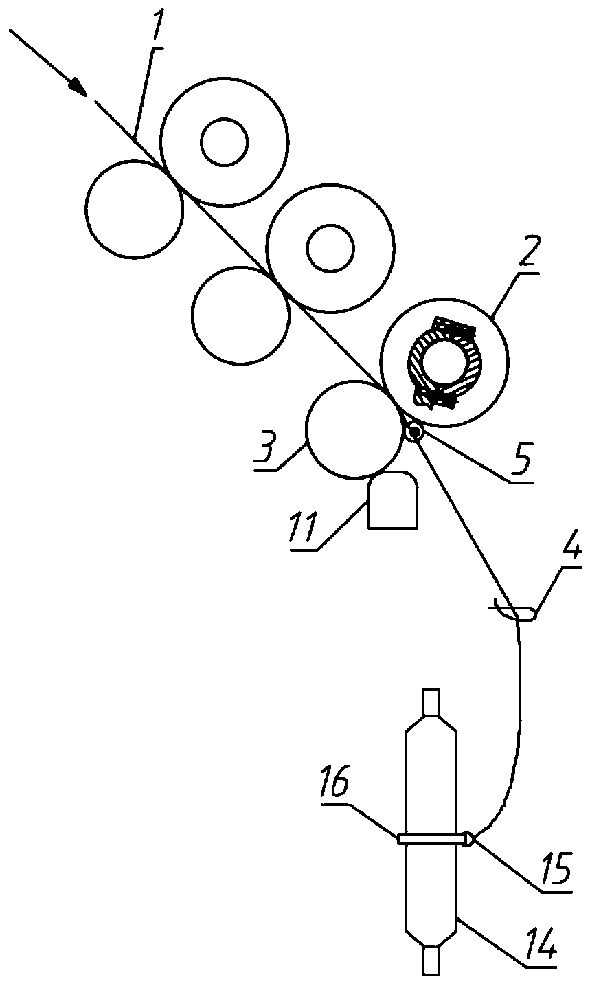
[0034] The two strands 1 are drawn out by the front top roller 2 and the front roller 3, and the distance between the two strands 1 is 3.5mm. Nipper area, so the strand 1 forms a twisting triangle 6, after the twisting triangle 6, the strand 1 obtains the twist passed from the convergence point 7 and becomes a single yarn 17;

[0035] After two single-ply yarns 17 are merged, they are further twisted into yarns similar to plying. When two single-ply yarns 17 are combined, they form a convergence point 7. At the convergence point 7, two single-ply yarns 17 single-ply yarns The included angle is 25 degrees.

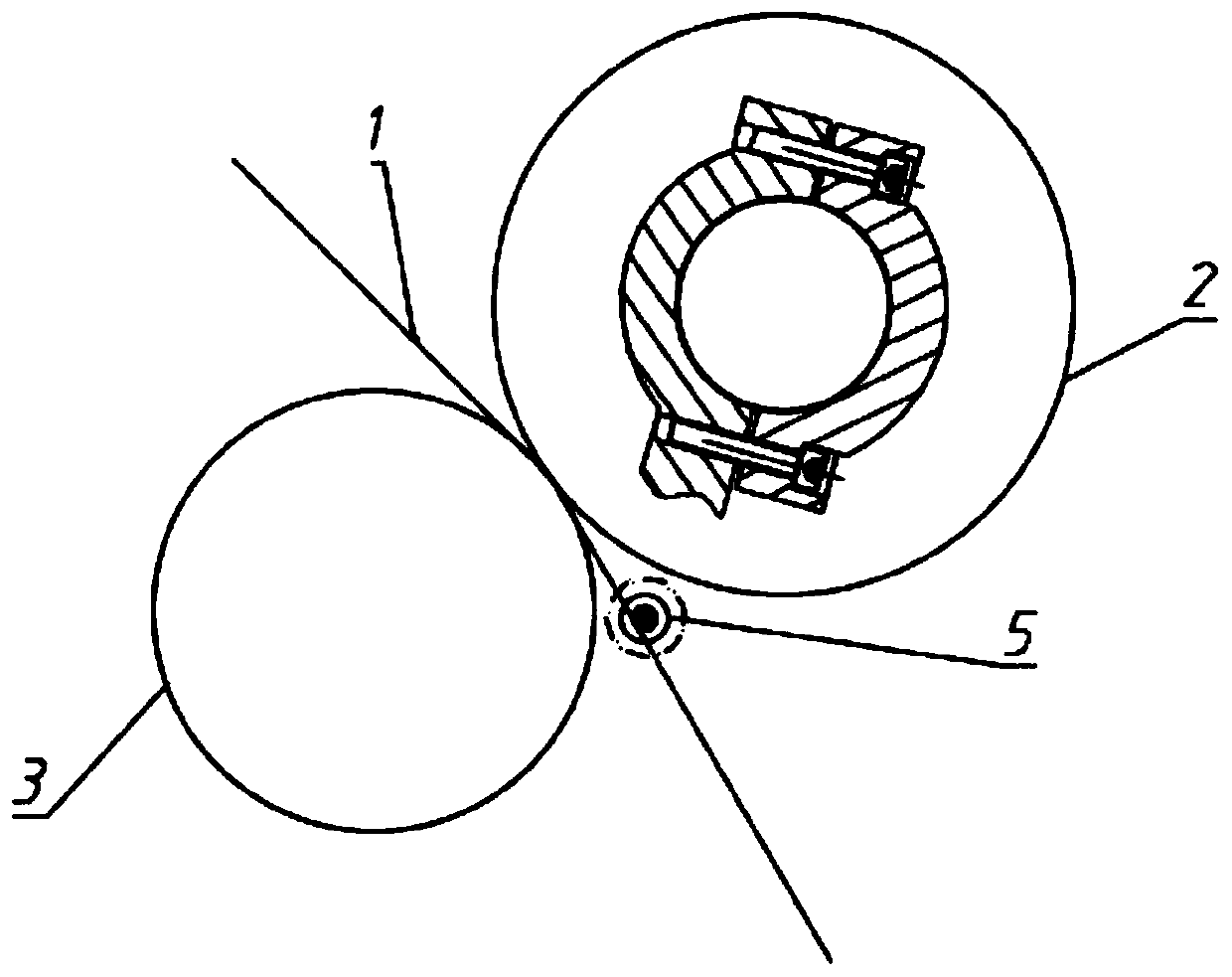
[0036] Such as Figure 1 to Figure 7 As shown, a siro spinning depilation device includes a depilation roller 5 arranged in the nip area formed by the front top roller 2 and the front roller 3, and the depilation roller 5 is free to rotate around the central axis.

[0037] The de-hairing roller 5 is specifically arranged between the front top roller 2 and the convergence po...

Embodiment 2

[0065] Such as Figure 8 As shown, in the present embodiment, the guide groove 9 on the de-hairing roller 5 is a V-shaped groove;

[0066] Preferably, the depth of the V-shaped groove is 0.5mm;

[0067] Preferably, the width of the upper end of the V-shaped groove is 0.8mm;

[0068] Preferably, the center distance between the two V-shaped grooves is 1.8mm;

[0069] Both sides of the V-shaped groove are provided with chamfers to make the yarn fall into the V-shaped groove smoothly.

[0070] The yarn enters the V-shaped groove. Since the V-shaped structure has a better binding effect on the yarn, the fibers protruding from the surface of the single-ply yarn 17 can be better rotated with the twisting and rotation of the single-ply yarn 17. Wrapped to the surface of the single yarn 17.


PUM

PropertyMeasurementUnit
diameteraaaaaaaaaa

Abstract

The invention discloses a siro spinning fiber removing device. A fiber removing roller which rotates freely around a central axis is arranged in a jaw region formed by a front leather roller and a front roller; the fiber removing roller is particularly arranged between the front leather roller and a convergence point and is close to the jaw region as much as possible; two guide grooves are formedin the outer circumferential surface of the fiber removing roller, and two single-strand yarns fall into two guide grooves respectively, wherein the guide grooves collect and gather the edges of the single-strand yarns, so that the fibers extending out of the surfaces of the single-strand yarns are rotated to wrap around the surfaces of the single-strand yarns along with the twisting rotation of the single-strand yarns, and after passing through the convergence point, the two single-strand yarns are twisted and wound together, and the fibers wrapped around the surfaces of the single-strand yarns are wrapped in the yarn, and therefore the fibers on the surface of the yarn is reduced, and the function of further reducing the fibers of the siro-spun yarn is achieved.

Description

technical field [0001] The invention relates to the field of textile machinery, in particular to a hairiness removal device for siro spinning. Background technique [0002] Compared with similar yarns spun by ordinary ring spinning methods, siro spun yarns have the advantages of high strength, less hairiness, and evenness. In particular, if other methods are used to process strands of the same thickness as siro spinning, it needs to go through three processes of spinning single yarn, plying and twisting, while using siro spinning can be completed in only one process. Therefore, Sai Network spinning also has the advantages of high efficiency and short process. Based on the above advantages, the application of siro spinning in the field of yarn is becoming more and more extensive. [0003] Siro spinning is to feed two rovings with a certain distance on the spinning frame. After drafting, the two single yarns and single-ply yarns are output by the front roller. back, giving ...

Claims


Application Information

Patent Timeline
Patent Type & Authority Applications(China)
IPC IPC(8): D01H1/00D01H5/22D01H5/72
CPCD01H1/00D01H5/22D01H5/72
Inventor 沈小林洪焱徐卫林刘可帅郭维琪
Owner WUHAN TEXTILE UNIV
Why Eureka
Try Eureka