Separator utilizing gears

A divider and gear technology, applied in conveyors, mechanical conveyors, transportation and packaging, etc., can solve problems such as inability to ensure stable transportation of clothes hangers

Pending Publication Date: 2020-05-01
SHANGHAI SANHE GARMENT LOGISTICS EQUIP MFG
View PDF0 Cites 0 Cited by
  • Summary
  • Abstract
  • Description
  • Claims
  • Application Information

AI Technical Summary

Problems solved by technology

The existing conveying system is prone to conveying accumulation

Method used


Image

  • Separator utilizing gears
  • Separator utilizing gears
  • Separator utilizing gears

Examples


Embodiment Construction

[0010] The technical solutions of the present invention will be clearly and completely described below in conjunction with the accompanying drawings. Apparently, the described embodiments are some of the embodiments of the present invention, but not all of them. Based on the embodiments of the present invention, all other embodiments obtained by persons of ordinary skill in the art without making creative efforts belong to the protection scope of the present invention.

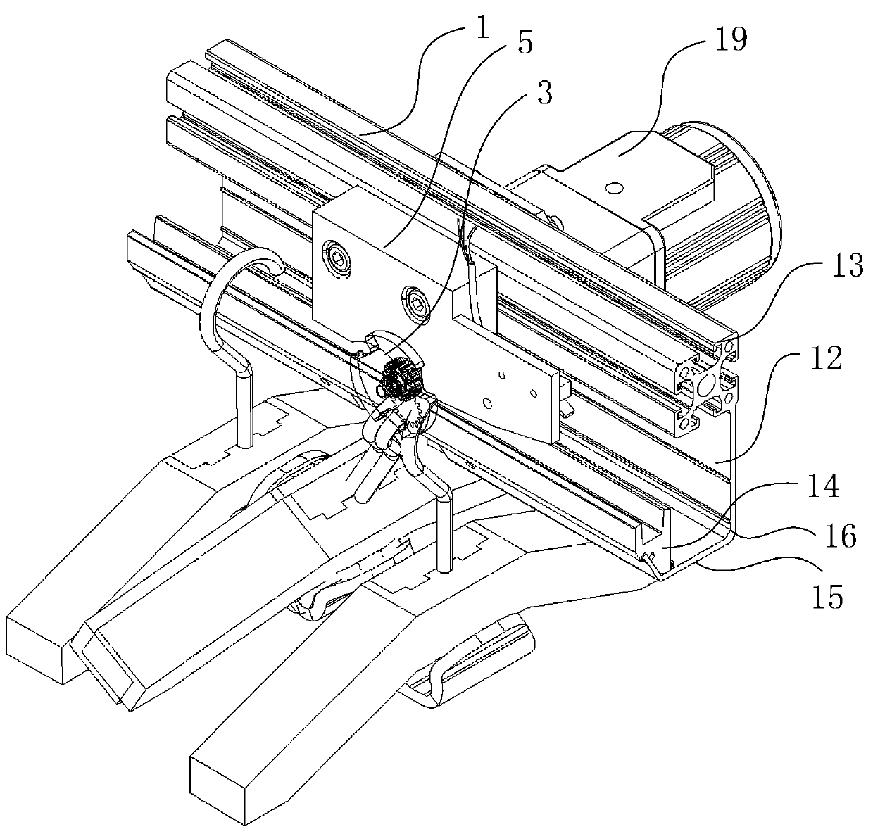
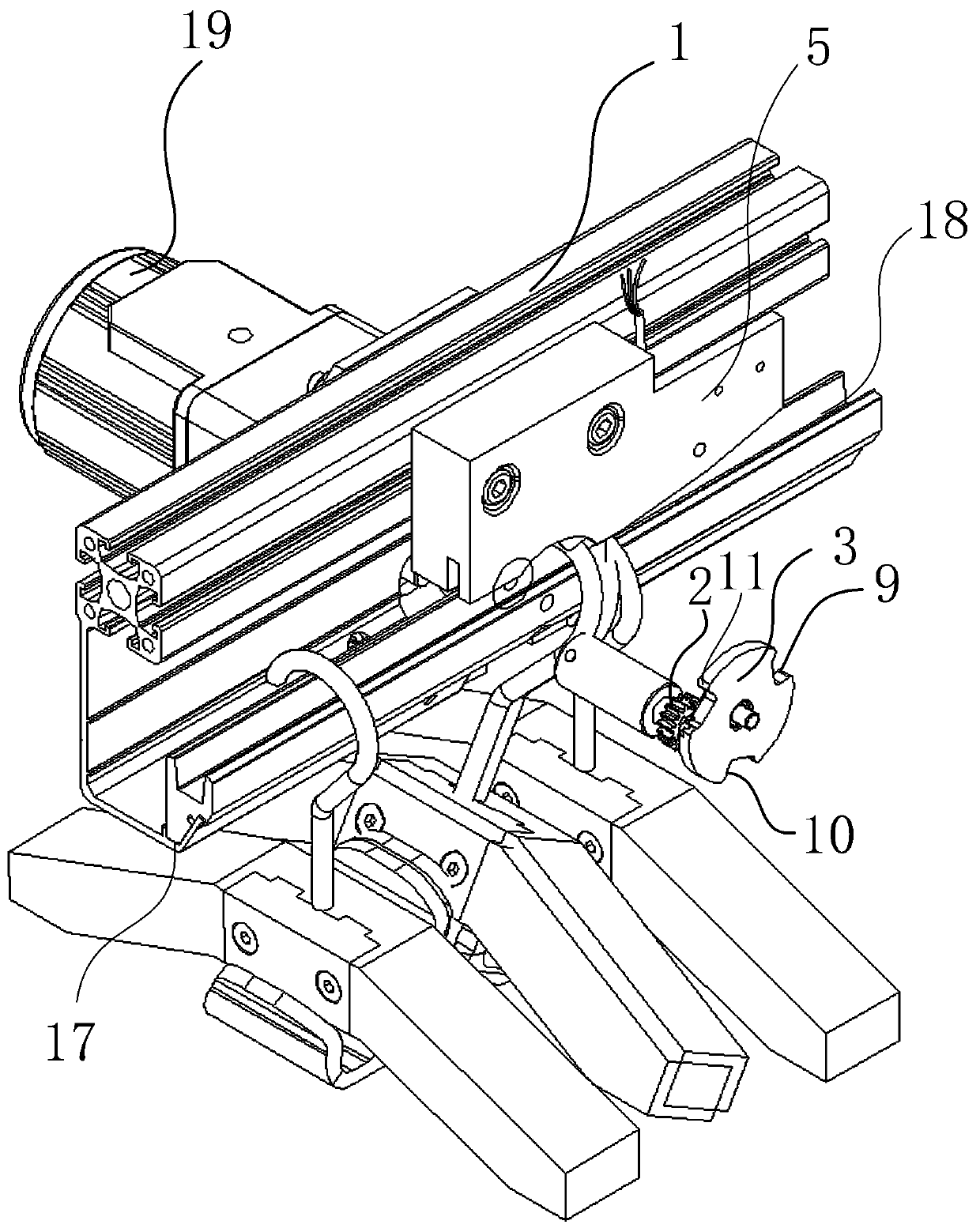
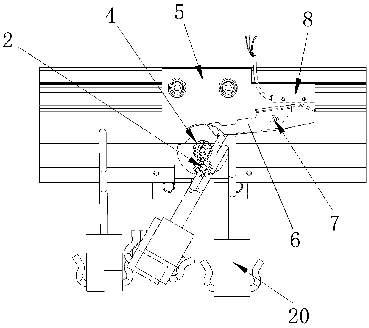
[0011] The present invention discloses a gear divider, such as figure 1 As shown in the figure, the conveying track 1 is included, the inner side of the conveying track 1 is provided with a stepping motor 19, the outside of the conveying track 1 is provided with a transmission gear 2 connected with the output shaft 21 of the stepping motor 1, and the outside of the conveying track 1 is also provided with There is a separation turntable 3, the center of the inner side of the separation turntable 3 is fixed with...


PUM


Abstract

The invention discloses a separator utilizing gears. The outer side of a conveying track is provided with a transmission gear connected with an output shaft of a stepping motor, a separation rotary disc is further arranged on the outer side of the conveying track, a driven gear is fixedly arranged at the center position of the inner side of the separation rotary disc, the transmission gear mesheswith the driven gear, the stepping motor drives the transmission gear to rotate to drive the driven gear to rotate; a sensing contact piece is movably connected with the inner side of a baffle througha contact piece rotating shaft, the inner side of the baffle is further provided with an inductor matched with the sensing contact piece, and the other end of the sensing contact piece is heavier than the one end of the sensing contact piece, so that in the stopped state, the one end of the sensing contact piece is tilted upwards to touch the inductor above; and three notch parts are distributedin the edge of the separation rotary disc at equal intervals, and a 120-degree interval is formed between adjacent notch parts. The stepping motor is started to rotate by 120 degrees, a clothes hangeris driven to rotate to the rear conveying track through the notch in the separation rotary disc, the previous process is repeated, and the purpose of continuous separation is achieved.

Description

technical field [0001] The present invention relates to the technical field of material conveying systems, in particular to a gear divider, and in particular to its mechanical connection structure. Background technique [0002] During the operation of the needle conveying system, sometimes the conveyed clothes are required to be conveyed evenly, so that when they are sent to the main conveying chain, only one piece of clothing can be hung in each conveying chain, and the sorting operation can be carried out. The existing conveying system is prone to conveying accumulation, which cannot guarantee the stable conveying of clothes hangers. Contents of the invention [0003] The object of the present invention is to provide a gear divider capable of separating and conveying the clothes racks on the conveying track one by one. The defects and deficiencies existing in the prior art are overcome. [0004] In order to achieve the above object, the technical solution of the presen...

Claims


Application Information

Patent Timeline
IPC IPC(8): B65G35/00
CPCB65G35/00
Inventor 郑培仪
Owner SHANGHAI SANHE GARMENT LOGISTICS EQUIP MFG
Why Eureka
Try Eureka