
Gate drive circuit and display panel

A gate drive circuit and gate drive technology, applied in the direction of static indicators, instruments, etc., can solve the problems of brightness and unevenness of horizontal dense lines on the display panel, so as to avoid horizontal dense lines and uneven brightness and darkness, improve display quality, The effect of avoiding picture quality problems

Active Publication Date: 2020-05-01
SHENZHEN CHINA STAR OPTOELECTRONICS SEMICON DISPLAY TECH CO LTD
View PDF6 Cites 23 Cited by
  • Summary
  • Abstract
  • Description
  • Claims
  • Application Information

AI Technical Summary

Problems solved by technology

[0004] The purpose of the present application is to provide a gate drive circuit and a display panel, to balance the fall time of the output scan signal of the gate drive unit connected to multiple clock signal lines in the gate drive circuit, and to avoid the capacitance difference of the clock signal lines from causing The display panel has problems such as horizontal dense lines and uneven brightness and darkness

Method used


Image

  • Gate drive circuit and display panel
  • Gate drive circuit and display panel
  • Gate drive circuit and display panel

Examples


Embodiment Construction

[0021] The technical solutions in the embodiments of the present application will be clearly and completely described below in conjunction with the drawings in the embodiments of the present application. Apparently, the described embodiments are only some of the embodiments of this application, not all of them. Based on the embodiments in this application, all other embodiments obtained by those skilled in the art without making creative efforts belong to the scope of protection of this application.

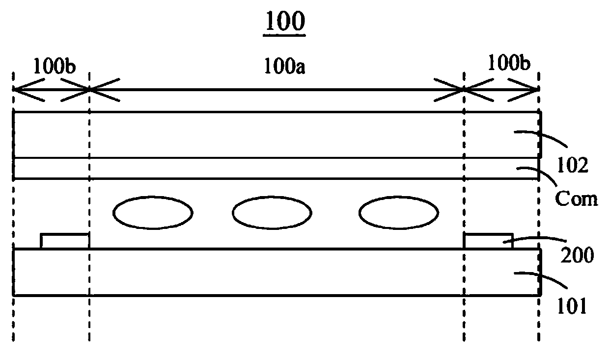
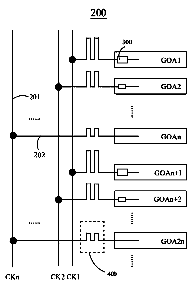
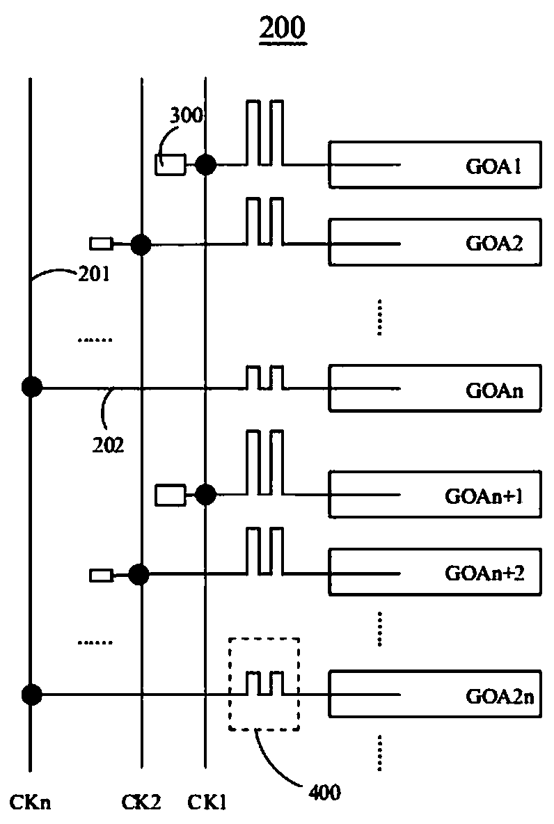
[0022] see figure 1 and figure 2 , figure 1 is a schematic diagram of the display panel of the embodiment of the present application, figure 2 for figure 1 The first schematic diagram of the gate drive circuit in the shown display panel. The display panel 100 is a liquid crystal display panel. The display panel 100 includes an array substrate 101 , a color filter substrate 102 and a liquid crystal layer disposed between the array substrate 101 and the color filter substra...


PUM


Abstract

The invention provides a gate drive circuit and a display panel. The gate drive circuit comprises N clock signal lines and a plurality of gate drive units, the N clock signal lines include a first clock signal line to an Nth clock signal line which are sequentially arranged on one side of the plurality of gate driving units. Each gate driving unit is connected with at least one clock signal line,and each clock signal line is provided with a capacitance compensation unit. The area of the capacitance compensation unit arranged on the first clock signal line is gradually increased or decreased relative to the area of the capacitance compensation unit arranged on the Nth clock signal line, the sum of the area of any one clock signal line and the area of the capacitance compensation unit arranged on the same clock signal line is equal to a preset area, and N is an integer greater than or equal to 2. By compensating the area difference among the plurality of clock signal lines, the problemsof horizontal dense lines, uneven brightness and the like of the display panel caused by capacitance difference of the clock signal lines due to the area difference are avoided.

Description

technical field [0001] The present application relates to the field of display technology, in particular to a gate drive circuit and a display panel. Background technique [0002] At present, 1G1D 8K products generally use a gate drive circuit (Gate On Array). However, the 1G1D 8K product scan line and data line have a large resistance-capacitance load (RC Loading), and the charging time is short. Among them, the scanning signal loaded by the scanning line of the 1G1D 8K product is extremely sensitive to the capacitance difference between multiple clock signal lines (CLOCK) in the gate drive circuit, and the large capacitance difference between different clock signal lines will cause the same There are differences in the scanning signal waveform loaded by the scanning line corresponding to the clock signal line, and there are screen display problems such as equidistant horizontal lines when displaying 1G1D 8K products. [0003] Therefore, it is necessary to propose a techn...

Claims


Application Information

Patent Timeline
Patent Type & Authority Applications(China)
IPC IPC(8): G09G3/36
CPCG09G3/3677G09G2320/0233
Inventor 熊珏金一坤赵斌张鑫赵军
Owner SHENZHEN CHINA STAR OPTOELECTRONICS SEMICON DISPLAY TECH CO LTD
Learn More