Control method for airplane ground power supply cable voltage drop compensation

A ground power supply and voltage drop compensation technology, applied in the direction of AC network voltage adjustment, etc., can solve the problems of inconvenient, cumbersome methods, and compensated voltage value errors, etc., and achieve the effect of fast dynamic response, clear physical meaning, and guaranteed stability

Active Publication Date: 2020-05-05
SICHUAN HANGDIAN MICRO ENERGY CO LTD
View PDF8 Cites 8 Cited by
  • Summary
  • Abstract
  • Description
  • Claims
  • Application Information

AI Technical Summary

Problems solved by technology

This method needs to be carried out step by step, and if the cable is replaced, the impedance and the compensated voltage value need to b

Method used


Image

  • Control method for airplane ground power supply cable voltage drop compensation
  • Control method for airplane ground power supply cable voltage drop compensation
  • Control method for airplane ground power supply cable voltage drop compensation

Examples


Embodiment 1

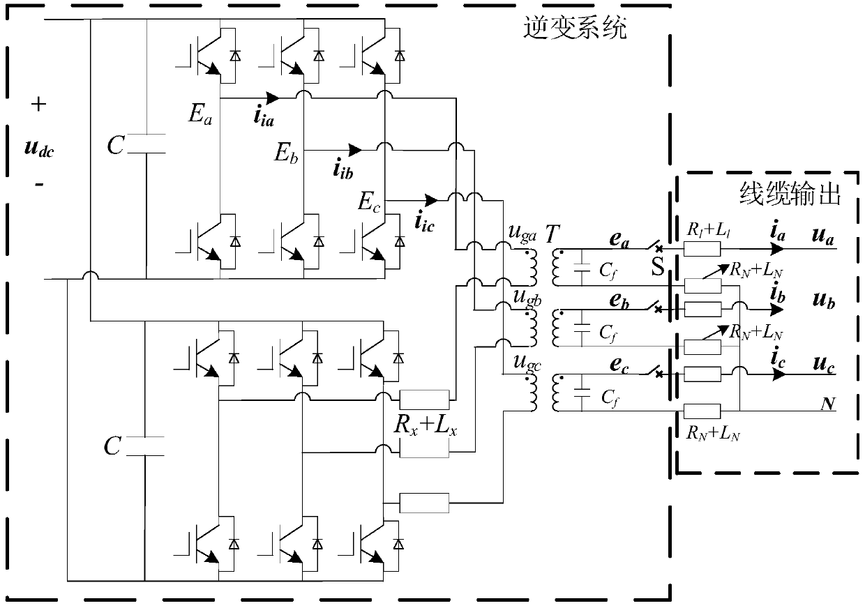
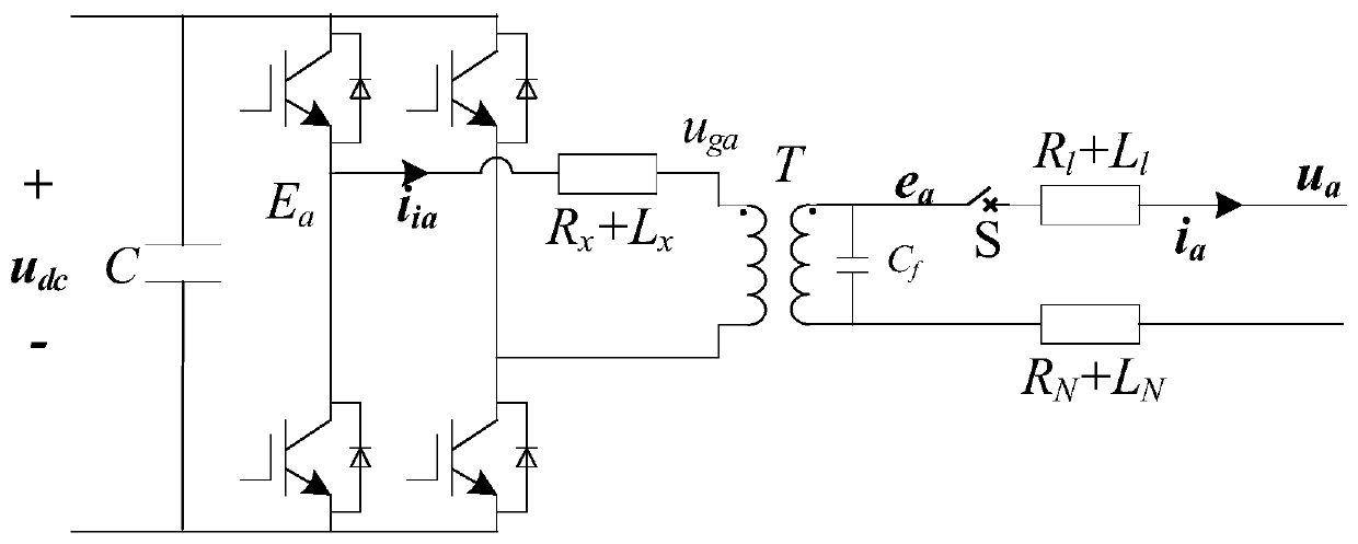
[0046] In order to better solve the cable voltage compensation, a cable voltage compensation inverter control strategy based on compensation voltage feed-forward is proposed, specifically a method for compensating the voltage drop of the aircraft ground power supply cable provided in this embodiment The control method adopts a three-phase six-arm parallel inverter in the power transmission cable of the aircraft ground power supply. The upper and lower bridge arms of the three-phase six-arm parallel inverter form a single-phase inverter, and each single-phase The inverter is controlled independently, which can effectively solve the problem of unbalanced load, such as figure 1 As shown in , it is a circuit topology diagram of a three-phase six-arm parallel inverter, which mainly consists of two parts: the inverter system and the cable output. The meanings of each parameter in the figure are as follows:

[0047] In its circuit, i ia i ib i ic Output current for each single-pha...

Embodiment 2

[0087] Based on the control method of the aircraft ground power cable voltage drop compensation provided in Embodiment 1, a control system applying the control method is provided in this embodiment, such as Figure 9 As shown, the system includes: three-phase six-arm parallel inverter, single-phase isolator, transmission cable, load, compensation loop PI regulator, voltage loop PI regulator, PWM and drive circuit, the three-phase six The output end of the bridge arm parallel inverter is connected to the single-phase isolator, the output end of the single-phase isolator is connected to the transmission cable, and the output end of the transmission cable is connected to the load, such as Figure 8 As shown, its working principle is as follows: separately collect the voltage u of the three phases at the output end of the transmission cable a , u b , u c , set the voltage given value u of the three phases at the output end of the transmission cable ref (u a_ref , u b_ref , u ...


PUM


Abstract

The invention discloses a control method for aircraft ground power supply cable voltage drop compensation, which belongs to the technical field of aircraft ground services. The method comprises the steps of building mathematic models for the cable output ends of all single-phase inverters, and obtaining a cable voltage balance relation under a d-q axis system; sampling and calculating each single-phase voltage at the output end of the cable, comparing each single-phase voltage with a given voltage value of each phase at the output end of the cable, and obtaining a voltage drop voltage udown ofeach phase on the power transmission cable through a compensation ring PI regulator; judging whether an output contactor is closed or not and whether the power transmission cable has output voltage or not so as to perform voltage drop compensation; and acquiring a new output voltage given value after voltage drop compensation, and controlling a three-phase six-bridge-arm parallel inverter based on the cable voltage balance relationship and the new output voltage given value, so as to improve the output voltage of the inverter and complete voltage drop compensation. The purpose of ensuring thestability of load voltage is achieved while the problem of voltage drop of the cable is solved.

Description

technical field [0001] The invention belongs to the technical field of aircraft ground services, and in particular relates to a control method for voltage drop compensation of aircraft ground power supply cables. Background technique [0002] Due to the implementation of the "oil-to-electricity" project for airports in recent years, aircraft ground power supplies have gradually been widely used in major airports. As the key equipment of aircraft ground power supply, three-phase inverter is the core of power supply for aircraft. As a bridging device between the power supply and the aircraft, the intermediate frequency inverter must have the ability to output high-quality voltage waveforms, so the output voltage is the control object of the entire device. When the stationary ground power supply supplies power to the aircraft, the cables connecting the two will produce a voltage drop due to reasons such as long-distance power transmission and impedance. The voltage drop will ...

Claims


Application Information

Patent Timeline
IPC IPC(8): H02J3/12
CPCH02J3/12
Inventor 周星宏郑尧韩鹤光
Owner SICHUAN HANGDIAN MICRO ENERGY CO LTD
Why Eureka
Try Eureka