
Power supply control device for electronic installation equipped with multiple batteries

An electronic device and power supply control technology, applied in battery circuit devices, secondary battery charging/discharging, circuit devices, etc., can solve the problems of loss of user data, shutdown, difficulty, etc., and achieve the effect of avoiding the problem of voltage drop

Inactive Publication Date: 2007-02-28
QUANTA COMPUTER INC
View PDF3 Cites 0 Cited by
  • Summary
  • Abstract
  • Description
  • Claims
  • Application Information

AI Technical Summary

Problems solved by technology

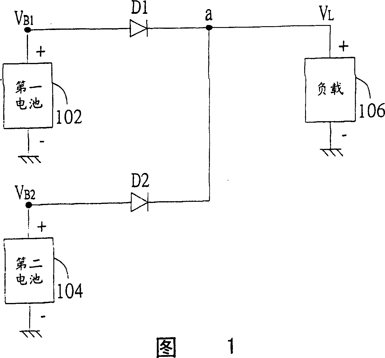
[0005] The disadvantage of the above power supply control device is that when the diode is turned on, the two poles of the diode will have a voltage drop of about 0.35~0.7 volts
In addition, if the power supply voltage of the battery is not high at that time, the above-mentioned method may cause the load to mistakenly think that the power of the battery is insufficient, and even forcibly shut down, resulting in the loss of user data and inconvenience in use
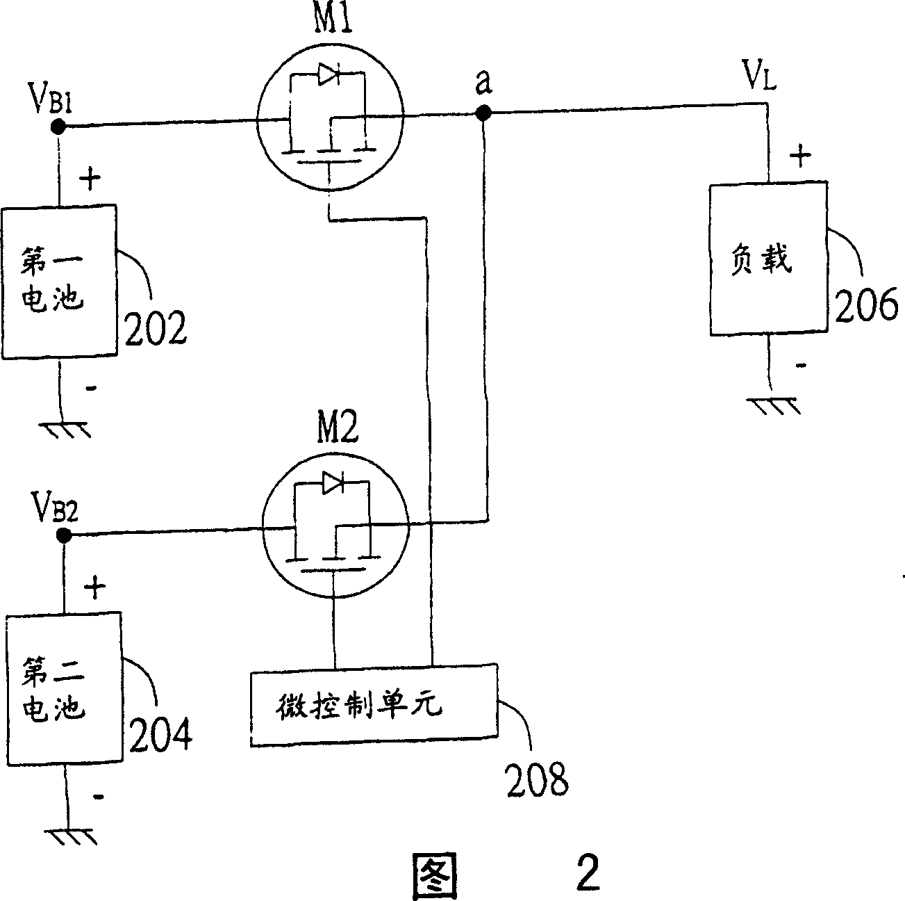
Also, if a new battery is added as a new power source for the load, it is necessary to use a software program to reset the action of the microcontroller, which is more difficult

Method used


Image

  • Power supply control device for electronic installation equipped with multiple batteries
  • Power supply control device for electronic installation equipped with multiple batteries
  • Power supply control device for electronic installation equipped with multiple batteries

Examples


Embodiment Construction

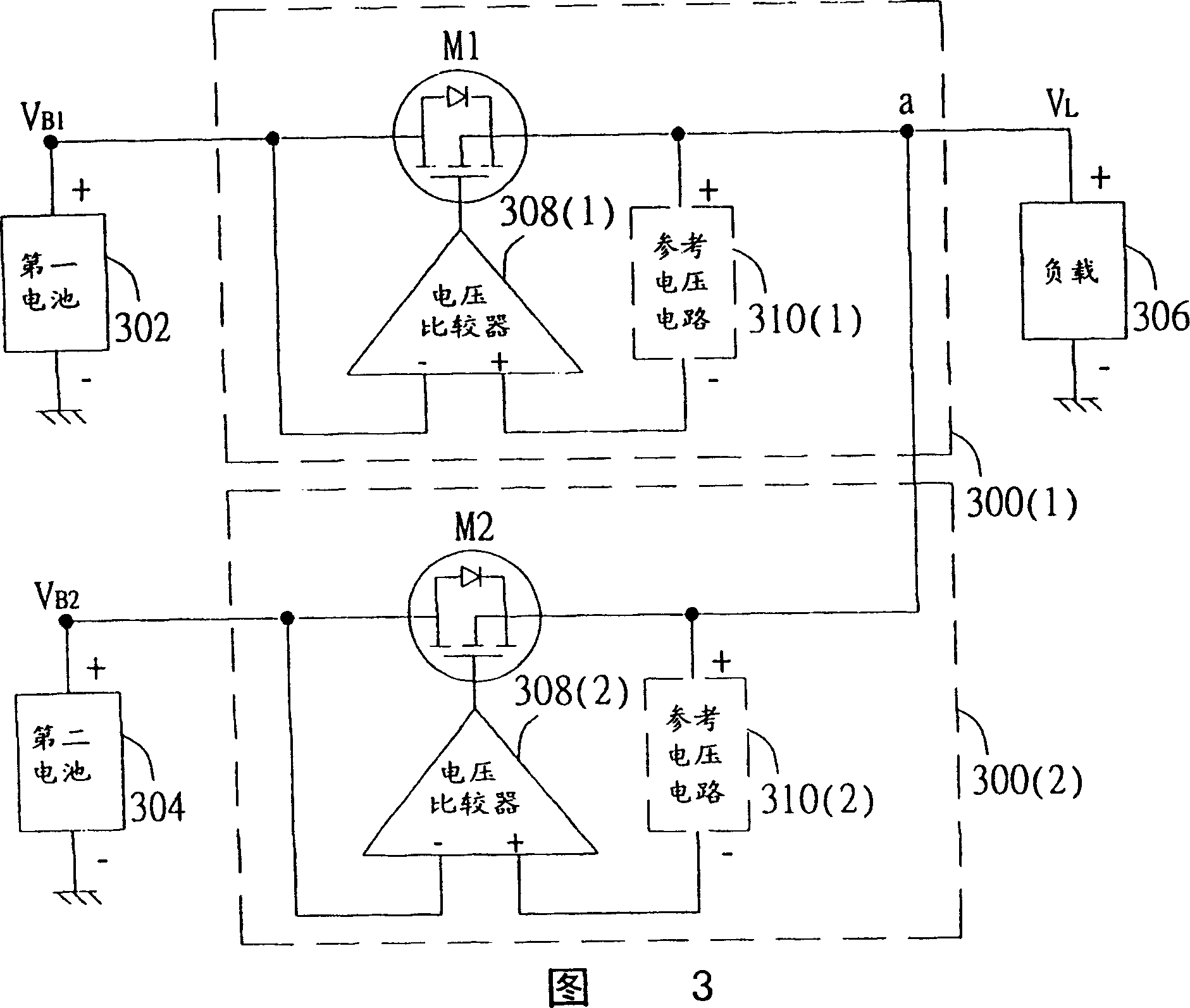
[0015] The power supply control device proposed by the present invention equips each battery with an independent power supply control device to control the power supply status of the battery, instead of controlling all batteries through a Micro Control Unit (MCU) as in the traditional method power supply status. In this way, when the load needs to add a new battery as a new power source, it is only necessary to couple a new power supply control device to the new battery and the load respectively, and there is no need to reset the action of the micro control unit with a software program , is relatively simple.

[0016] Please refer to FIG. 3 , which is a circuit block diagram of a power supply control device for a portable device equipped with dual batteries proposed by the present invention. The following takes the power supply control device 300 ( 1 ) coupled to the first battery 302 as an example to illustrate the coupling relationship and working principle of the component...


PUM


Abstract

The power supply controller consists of transistor, reference voltage circuit and voltage comparator circuit. The transistor is connected to battery and the electronic equipment; the reference voltage circuit is connected to the electronic equipment and the voltage comparator circuit for outputting regulated load voltage, which is the difference between the load voltage and the reference voltageand has the uncertainty caused by the offset voltage of the voltage comparator circuit eliminated; and the voltage comparator circuit is connected to the reference voltage circuit, the battery and the transistor to control the transistor to be switched on when the power supply voltage is higher than the regulated load voltage or switched off otherwise. The present invention aims at providing oneequivalent ideal diode connected serially between the battery and the electronic equipment.

Description

(1) Technical field [0001] The present invention relates to a power supply control device, and more particularly to a power supply control device for an electronic device equipped with multiple batteries. (2) Background technology [0002] With the rapid development of science and technology, the advent of digital electronic products has brought more convenient life to human beings. The rapid development of various portable devices, such as mobile phones, notebook computers or personal digital assistants (Personal Digital Assistance, PDA), has greatly improved the convenience of human life and the efficiency of work. [0003] The portable device can completely rely on its equipped battery as a power source to provide the required power without an external power supply. The working time of a portable device without an external power source depends on how long the battery can supply power continuously and stably. At present, a plurality of battery packs are generally used to...

Claims


Application Information

Patent Timeline
Patent Type & Authority Patents(China)
IPC IPC(8): H02J7/00H01M10/44H02J7/34
CPCY02E60/10
Inventor 陈升峰
Owner QUANTA COMPUTER INC
Learn More