A steering transmission system and vehicle

A steering transmission and bogie technology, which is applied to vehicle parts, steering mechanisms, steering tie rods, etc., can solve the problem of machining errors and the inability of the steering tie rods to be properly connected between the steering knuckle arm and the corresponding intermediate rocker arm, and the steering tie rod. Long end distance and other issues

Active Publication Date: 2020-10-27
ZHENGZHOU YUTONG HEAVY IND
View PDF6 Cites 0 Cited by
  • Summary
  • Abstract
  • Description
  • Claims
  • Application Information

AI Technical Summary

Problems solved by technology

[0005] The purpose of the present invention is to provide a steering transmission system to solve the problem that the distance between the two ends of the steering rod is relatively short or long due to the existence of machining errors in the prior art, so that the steering rod cannot be properly connected to the steering knuckle. The technical problem between the arm and the corresponding intermediate rocker arm; the purpose of the present invention is also to provide a vehicle to solve the problem in the prior art that due to the existence of machining errors, the distance between the two ends of the steering rod is relatively short or long, so that The technical problem that the straight tie rod cannot be well connected between the steering knuckle arm and the corresponding intermediate rocker arm

Method used


Image

  • A steering transmission system and vehicle
  • A steering transmission system and vehicle
  • A steering transmission system and vehicle

Examples


Embodiment 1

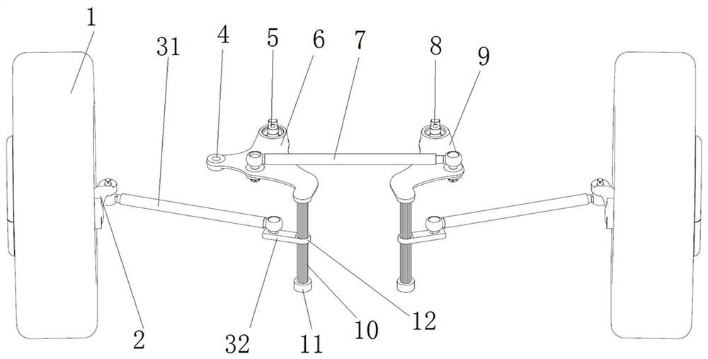
[0068] like figure 1 As shown, the steering transmission system is arranged between two wheel assemblies 1 . The steering transmission system includes a bogie, a knuckle arm tie rod and a steering knuckle arm 2, the bogie is fixedly connected with a vertical arm 10, and the knuckle arm tie rod includes a first tie rod unit 31 and a second tie rod unit 32, and the second tie rod unit 32 is far away from the first tie rod unit. One end of a tie rod unit 31 is slidably fitted on the vertical arm 10, and the end of the first tie rod unit 31 away from the second tie rod unit 32 is hinged to the end of the steering knuckle arm 2; the number of steering knuckle arms 2 is two, and each steering knuckle The end of the arm 2 away from the first tie rod unit 31 is fixedly connected to the steering knuckle of the corresponding wheel assembly 1, so that when the bogie rotates, the knuckle arm tie rod is driven to drive the knuckle arm 2 to move, thereby realizing the steering of the wheel ...

Embodiment 2

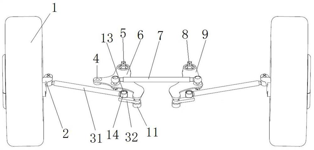
[0077] like figure 2 As shown, the difference from Embodiment 1 is that, taking the left side as an example, one end of the second tie rod unit 32 is hinged on the driving arm 6, and the other end of the second tie rod unit 32 is provided with a spline shaft 13, the first One end of the tie rod unit 31 is hinged on the steering knuckle arm 2, and the other end is provided with a spline sleeve 14, and the spline sleeve 14 on the first tie rod unit 31 is sleeved on the spline shaft 13 on the second tie rod unit 32, so as to Adjustment of the angle between the first rod unit 31 and the second rod unit 32 in the horizontal direction is realized. In other embodiments, the spline shaft can be arranged on the first tie rod unit, and the spline sleeve can be arranged on the second tie rod unit.

[0078] It should be noted that the spline shaft and the spline sleeve in this embodiment cannot move relative to each other in the axial direction of the spline shaft.

Embodiment 3

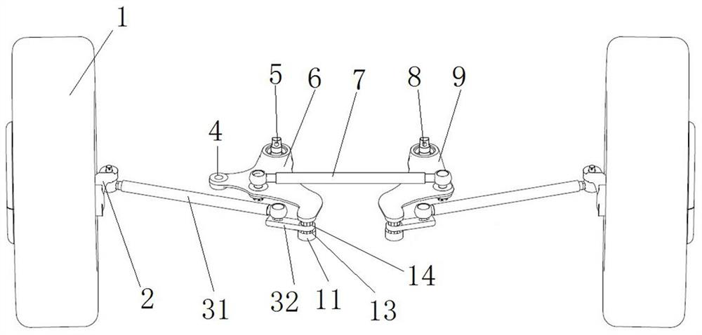
[0080] like image 3 As shown, the difference from Embodiment 1 is that the vertical arm 10 is a spline shaft, the length of the spline shaft is relatively short, and the second pull rod unit 32 is limited between the stopper 11 and the driving arm 6 .


PUM


Abstract

The invention relates to a steering transmission system and a vehicle. The steering transmission system comprises a bogie, two steering knuckle arms and knuckle arm pull rods, wherein the bogie is rotatingly assembled on a frame, the bogie is provided with a driving connection part, and the driving connection part is used for being in transmission connection with a steering gear, so as to achievethe rotation of the bogie on the frame; the two steering knuckle arms are arranged on the two sides, in the width direction of the frame, of the bogie correspondingly; the knuckle arm pull rod is arranged between the bogie and the corresponding steering knuckle arm; the knuckle arm pull rod comprises at least two pull rod units, the connecting ends of any two adjacent pull rod units form a rotation stopping joint, the rotation stopping joint can adjust the included angle between the two corresponding pull rod units in the horizontal direction, the pull rod unit at the head end is in sphericalhinge with the bogie, and the pull rod unit at the tail end is in spherical hinge with the corresponding knuckle arm. The distance between the two ends of the knuckle arm pull rod is adjustable, thenthe two ends of the knuckle arm pull rod can be well connected between the steering knuckle arm and the corresponding middle rocker arm, and the stability of power transmission is guaranteed.

Description

technical field [0001] The invention relates to a steering transmission system and a vehicle. Background technique [0002] The independent suspension usually adopts a disconnected steering trapezoid, and its advantages are: the disconnected steering trapezoid cooperates with the independent suspension of the front wheels, which can ensure that when one side of the wheel jumps up and down, it will not affect the other side of the wheel. [0003] The Chinese patent with the authorized notification number CN201415706Y discloses a steering system for air independent suspension. The steering system includes a steering gear and a steering linkage. The left and right middle rocker arms, middle tie rods and straight steering rods are composed; the left and right middle rocker arms are respectively connected to the frame through pin shafts, the two ends of the middle tie rods are hinged in the middle of the left and right middle rocker arms, and the left and right tie rods are two ...

Claims


Application Information

Patent Timeline
Patent Type & Authority Patents(China)
IPC IPC(8): B62D3/02B62D7/20
CPCB62D3/02B62D7/20
Inventor 金鑫贾文学徐琳王向阳薛现振郑长波倪四红王守方
Owner ZHENGZHOU YUTONG HEAVY IND
Why Eureka
Try Eureka