
Emergency stop triggering device for steel strand folding forming

A technology of triggering device and steel strand, which is applied in the directions of transportation and packaging, transportation of filamentous materials, and processing of thin materials, etc., can solve problems such as affecting baling forming, affecting operation, and working fatigue, and achieves good practical use value. Eliminate cumbersome and laborious effects

Pending Publication Date: 2020-05-08
湖北军龙钢业有限公司
View PDF0 Cites 0 Cited by
  • Summary
  • Abstract
  • Description
  • Claims
  • Application Information

AI Technical Summary

Problems solved by technology

[0002] The steel strand is twisted into one strand by a number of steel wires with smaller diameters through a specific rotating and closing device to meet the requirements of use. After the twisting process is completed, it needs to be rolled up by a roller to form a bundle. It is convenient for packaging and transshipment. In the above process, the staff often need to keep a close eye on the operation table and the production line. When a roll is about to be completed, it is necessary to quickly activate the emergency stop button so that the drum and the pay-off equipment in front can be stopped quickly. , which is easy to cause work fatigue for the operators waiting by the production line. Once they do not stop in time, the drum will continue to rotate, which will affect the bundling and forming, and then affect the subsequent operation.

Method used


Image

  • Emergency stop triggering device for steel strand folding forming
  • Emergency stop triggering device for steel strand folding forming
  • Emergency stop triggering device for steel strand folding forming

Examples


Embodiment Construction

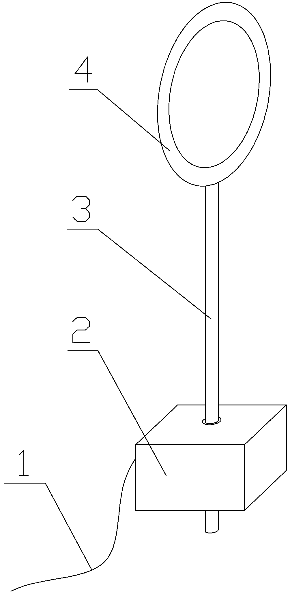
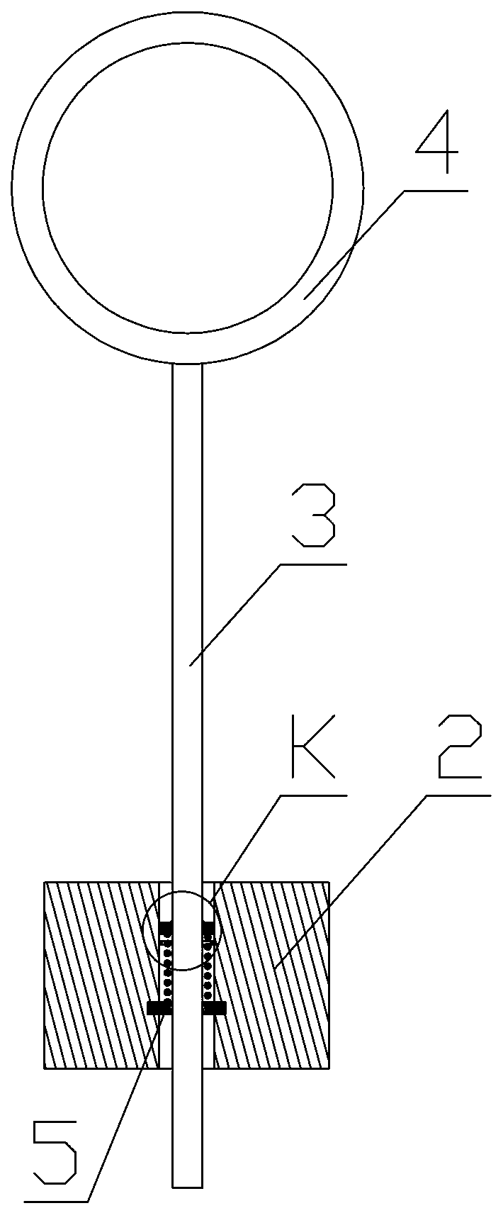
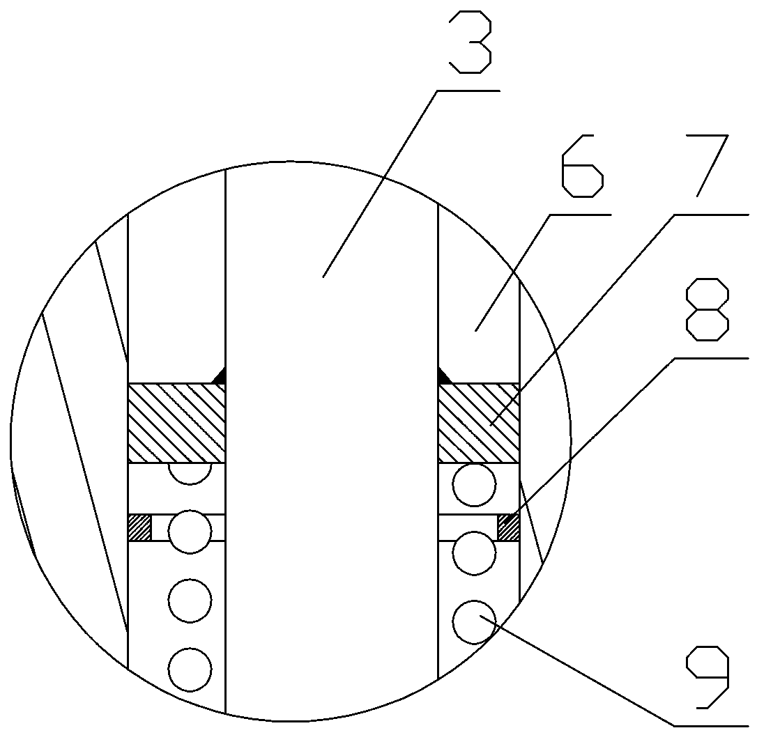
[0013] see Figure 1-Figure 4 , the present invention is an emergency stop trigger device for steel strands to be folded together and formed. It has a base 2, a through hole 6 from top to bottom is arranged in the center of the base, and a spring seat plate is fixed at the lower position in the middle of the through hole. 5. There is a column perforation at the center of the spring seat plate. A column 3 is installed in the hole of the column. A steel strand trigger ring 4 is fixed on the top of the column. A sliding block 7 is fixed on the column. The sliding block It is located in the through hole above the spring seat plate and slides up and down along the inner wall of the through hole. A buffer spring 9 is also set on the column. The upper end of the buffer spring is connected to the bottom of the sliding block, and the lower end of the buffer spring is connected to the The above spring seat plate is fixedly connected; a pressure sensor 8 is also fixed on the inner wall o...


PUM


Abstract

The invention relates to an emergency stop triggering device for steel strand folding forming. The emergency stop triggering device is provided with a base, wherein a top-down through hole is formed in the center of the base, and one spring seat plate is fixedly arranged at the lower position of the middle of the through hole; a stand column penetrating hole is formed in the center of the spring seat plate, one stand column is arranged in the stand column penetrating hole in a penetrating mode, and one steel strand triggering ring is fixedly arranged at the top end of the stand column; and onesliding block is fixedly arranged on the stand column, one buffer spring is further arranged on the stand column in a sleeving mode, the upper end of the buffer spring is connected with the bottom ofthe sliding block, the lower end of the buffer spring is fixedly connected with the upper face of the spring seat plate, and one pressure sensor is also fixedly arranged on the inner side wall of thethrough hole between the sliding block and the spring seat plate. The device is very simple in structural design, can quickly trigger the emergency stop operation, does not need workers to carry outcheck and process at any time, liberates a part of energy of the operators, and reduces the working fatigue degree of the operators.

Description

technical field [0001] The invention relates to the technical field of steel strand production equipment, in particular to an emergency stop trigger device for closing and forming steel strands. Background technique [0002] The steel strand is twisted into one strand by a number of steel wires with smaller diameters through a specific rotating and closing device to meet the requirements of use. After the twisting process is completed, it needs to be rolled up by a roller to form a bundle. It is convenient for packaging and transshipment. In the above process, the staff often need to keep a close eye on the operation table and the production line. When a roll is about to be completed, it is necessary to quickly activate the emergency stop button so that the drum and the pay-off equipment in front can be stopped quickly. , This is easy to cause work fatigue for the operators waiting by the production line. Once they do not stop in time, the drum will continue to rotate, which...

Claims


Application Information

Patent Timeline
Patent Type & Authority Applications(China)
IPC IPC(8): B65H63/08
CPCB65H63/08B65H2701/35B65H2553/80
Inventor 陈世云
Owner 湖北军龙钢业有限公司
Learn More