
Elasticity test tool for steel cable baffle ring for hole and mandrel assembly thereof

A steel wire retaining ring, elasticity test technology, applied in the direction of elasticity testing, machine/structural component testing, measuring device, etc. damage effect

Inactive Publication Date: 2020-05-08
河南航天精工制造有限公司
View PDF5 Cites 0 Cited by
  • Summary
  • Abstract
  • Description
  • Claims
  • Application Information

AI Technical Summary

Problems solved by technology

[0006] The object of the present invention is to provide a kind of elastic test tooling of the steel wire retaining ring for holes, to solve the technical problem that the elasticity test tooling in the prior art needs to be manually adjusted and aligned during the test, resulting in cumbersome operation and easy damage to the steel wire retaining ring for holes Problem: A mandrel assembly for elastic test tooling of the steel wire retaining ring for the hole is also provided to solve the problem that the mandrel fails to cooperate with the sleeve when pushing the steel wire retaining ring for the hole in the prior art, resulting in easy damage to the hole. Technical problems of steel wire retaining ring

Method used


Image

  • Elasticity test tool for steel cable baffle ring for hole and mandrel assembly thereof
  • Elasticity test tool for steel cable baffle ring for hole and mandrel assembly thereof
  • Elasticity test tool for steel cable baffle ring for hole and mandrel assembly thereof

Examples


Embodiment Construction

[0036] In order to make the object, technical solution and advantages of the present invention clearer, the present invention will be further described in detail below in conjunction with the accompanying drawings and embodiments. It should be understood that the specific embodiments described here are only used to explain the present invention, and are not intended to limit the present invention, that is, the described embodiments are only some of the embodiments of the present invention, but not all of the embodiments. The components of the embodiments of the invention generally described and illustrated in the figures herein may be arranged and designed in a variety of different configurations.

[0037] Accordingly, the following detailed description of the embodiments of the invention provided in the accompanying drawings is not intended to limit the scope of the claimed invention, but merely represents selected embodiments of the invention. Based on the embodiments of the...


PUM


Abstract

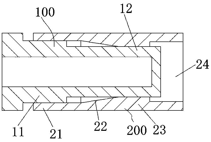
The invention relates to the field of mechanical fastener detection, in particular to an elasticity test tool for a steel cable baffle ring for a hole and a mandrel assembly of the elasticity test tool. The mandrel assembly comprises a mandrel, a positioning ring body, a guide matching surface, wherein the positioning ring body is coaxially and fixedly arranged outside the mandrel in a sleeving mode, and the positioning ring body and the front end of the mandrel are spaced in the radial direction to form an annular channel allowing a sleeve to be oppositely inserted; the guide matching surfaceis arranged on the inner side of the positioning ring body and corresponds to the annular channel, and the guide matching surface is used for being matched with the outer peripheral surface of the sleeve to guide the relative movement of the mandrel relative to the sleeve; and the positioning ring body extends forwards by a certain length, so as to ensure that the guide matching surface of the positioning ring body is in guide fit with the outer peripheral surface of the sleeve when the front end of the mandrel is pushed to the front of the steel cable baffle ring for the hole. Before the mandrel abuts against the steel cable baffle ring for the hole, movement of the mandrel relative to the sleeve can be guided by means of matching between the positioning ring body and the periphery of the sleeve, thereby guaranteeing that the mandrel and the sleeve are coaxially arranged and move along the axis and the mandrel can be aligned with the steel cable baffle ring for the hole to conduct pushing.

Description

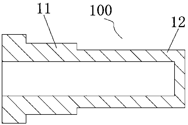
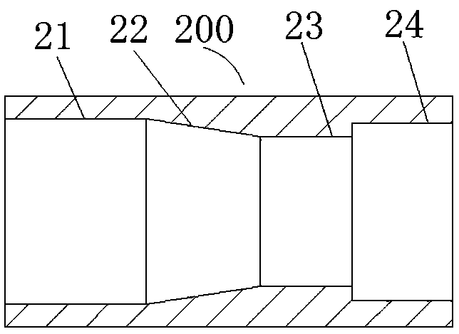
technical field [0001] The invention relates to the field of detection of mechanical fasteners, in particular to an elastic test tool for a steel wire retaining ring for a hole and a mandrel assembly thereof. Background technique [0002] For the elasticity test of the steel wire retaining ring for the hole, GB / T959.2-86 gives the specific test tooling and test procedures, in which the structure of the test tooling is as follows Figure 1 to Figure 3 As shown, the test tooling includes a mandrel 100 and a sleeve 200. During the test, the steel wire retaining ring for the hole is put into the sleeve 200, the mandrel 100 pushes the steel wire retaining ring for the hole out of the sleeve 200, and the test is performed three times continuously. Then measure the size of the wire retaining ring for the hole. Wherein, both the setting mandrel 100 and the sleeve 200 have an end inserted into each other as a front end. [0003] The structure of mandrel 100 is as figure 2 As shown...

Claims


Application Information

Patent Timeline
Patent Type & Authority Applications(China)
IPC IPC(8): G01M5/00
CPCG01M5/0075
Inventor 孙美丽寇景玲肖亚南陈秋占吕慧慧莫琳聪赵俊龙程莉莉翁玉峰
Owner 河南航天精工制造有限公司
Learn More