Eureka AIR delivers breakthrough ideas for toughest innovation challenges, trusted by R&D personnel around the world.

Automatic sample conveying device

A sample-feeding and automatic technology, applied in measuring devices, material analysis by optical means, instruments, etc., can solve the problems of installation and maintenance difficulties, the crucible stuck in the furnace mouth, affecting the analysis speed, etc., to achieve convenient installation, debugging and maintenance. Fast, convenient installation and maintenance, not easy to deform the effect of precision

Inactive Publication Date: 2010-09-08
CHANGSHA KAIYUAN INSTR
View PDF5 Cites 5 Cited by
  • Summary
  • Abstract
  • Description
  • Claims
  • Application Information

AI Technical Summary

Problems solved by technology

[0004] Through research on the prior art, the applicant found that in the above application documents, when the crucible carrying the sample is transferred to the furnace mouth, the chain with chain plate mechanism is used for transmission, and there are the following problems: 1. The chain with chain plate mechanism is composed of at least two Composed of two chains and multiple chain plates, there are many parts, and it is difficult to install and maintain
2. Due to the high temperature at the furnace mouth and the chain itself, the chain is prone to deformation and elongation after working for a long time, resulting in low positioning accuracy during transmission and prone to errors, thus affecting the experimental results
3. The combustion tube of the high-temperature furnace is circular, and the bracket for conveying the crucible is a flat plate. When a large number of crucibles are fed into or pulled out of the combustion tube from the bracket, it is easy to deflect the crucible, causing the crucible to be stuck in the furnace mouth, affecting Analysis speed

Method used


Image

  • Automatic sample conveying device
  • Automatic sample conveying device
  • Automatic sample conveying device

Examples


Embodiment Construction

[0064] In order to enable those skilled in the art to better understand the technical solutions in the present application, the technical solutions in the embodiments of the present application will be clearly and completely described below in conjunction with the drawings in the embodiments of the present application. Obviously, the described The embodiments are only some of the embodiments of the present application, but not all of them. Based on the embodiments in this application, all other embodiments obtained by persons of ordinary skill in the art without creative efforts shall fall within the scope of protection of this application.

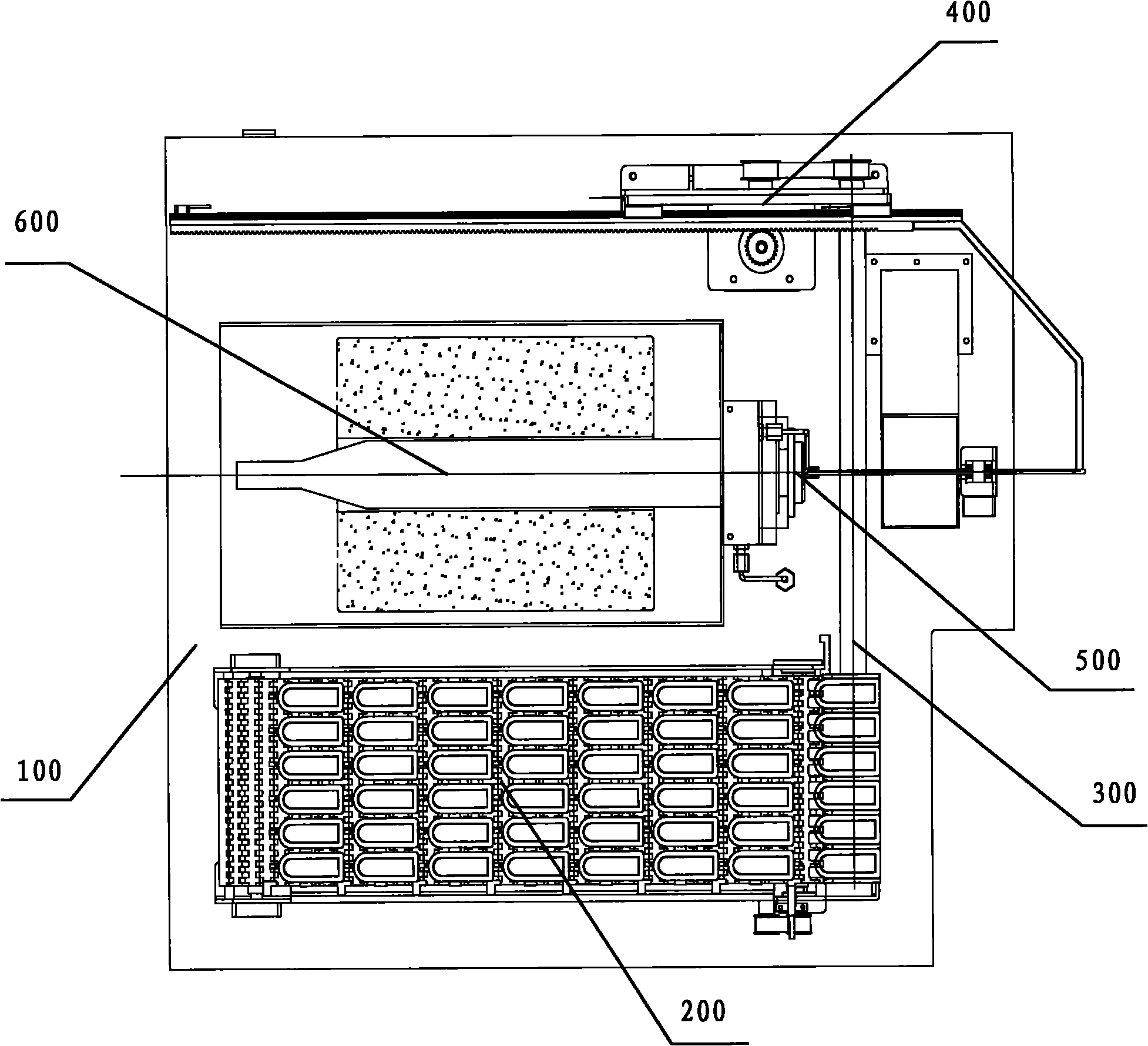
[0065] figure 1 The top view of the automatic sample feeding device provided by the embodiment of this application.

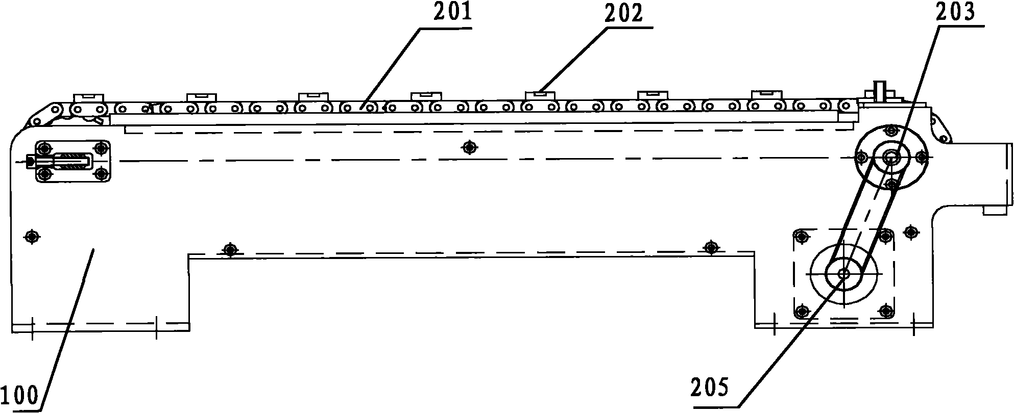
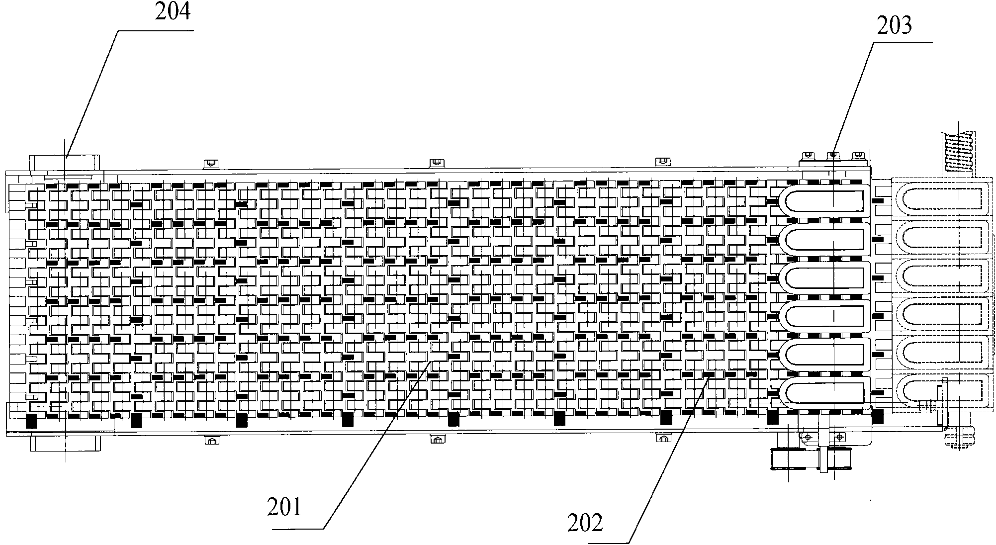
[0066] Such as figure 1 As shown, the automatic sample delivery device includes: a support frame 100, a mesh belt transmission mechanism 200, a screw transmission mechanism 300, a push rod mechanism 400 and a furnace mou...


PUM


Abstract

The invention discloses an automatic sample conveying device, which comprises a support frame, a mesh-belt conveying mechanism, a lead-screw conveying mechanism, a push rod mechanism and a furnace opening guide block, wherein the mesh-belt conveying mechanism is arranged on the support frame and is used for placing crucible pots and conveying the crucible pots in batches, the lead-screw conveyingmechanism is arranged on the support frame, and is used for conveying the crucible pots conveyed by the mesh-belt conveying mechanism to a stokehole, the push rod mechanism is arranged on the supportframe, is used for pushing the crucible pots conveyed to the stokehole by the lead-screw conveying mechanism into a furnace cavity, and can pull out the crucible pots out of the furnace cavity, and the furnace opening guide block is arranged at the stokehole and is used for making the push rod mechanism smooth push the crucible pots into the furnace cavity or smoothly pull out the crucible pots. The automatic sample conveying device can automatically control the sample conveyance in batches, the whole process is completely automatic without manual operation, and the labor can be saved. In addition, the conveyance precision is high, and the personal error is reduced.

Description

technical field [0001] The present application relates to the field of coal quality analysis instruments, in particular to an automatic sample feeding device for coal quality analysis instruments. Background technique [0002] In the series of coal quality analysis instruments, in order to measure the content of sulfur and other substances in the combustibles, the crucible carrying the combustibles is often accurately placed in the high-temperature constant temperature zone of the silicon carbon furnace, and the combustibles are burned. And through infrared light to measure the content index of sulfur or other substances. This infrared light sulfur meter is used to measure the sulfur content in combustibles, and has the advantages of accuracy and speed. [0003] Due to the high labor intensity and slow speed of manual sample delivery, the possibility of stakeout errors is relatively high, and the speed of manual sample delivery is inconsistent, resulting in inconsistent tim...

Claims


Application Information

Patent Timeline
Patent Type & Authority Applications(China)
IPC IPC(8): G01N35/02G01N21/17
Inventor 罗建文陈立孙洪俊蒋天傲
Owner CHANGSHA KAIYUAN INSTR
Why Eureka
Eureka Blog
Learn More