Earphone control structure

A control structure and earphone technology, which is applied in earpiece/earphone accessories, earphone mechanical/electronic switch, loudspeaker, etc., can solve the problem of inconvenient switching of earphones, and achieve the effect of convenient adjustment and user-friendliness

Active Publication Date: 2020-05-08
UBTECH ROBOTICS CORP LTD
View PDF10 Cites 0 Cited by
  • Summary
  • Abstract
  • Description
  • Claims
  • Application Information

AI Technical Summary

Problems solved by technology

[0003] The purpose of this application is to provide a headset control structure, aiming to solve the problem of inconvenient switching between different working states of the headset in the prior art

Method used


Image

  • Earphone control structure
  • Earphone control structure
  • Earphone control structure

Examples


specific Embodiment approach

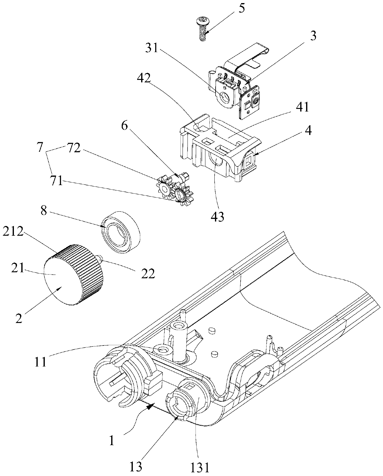
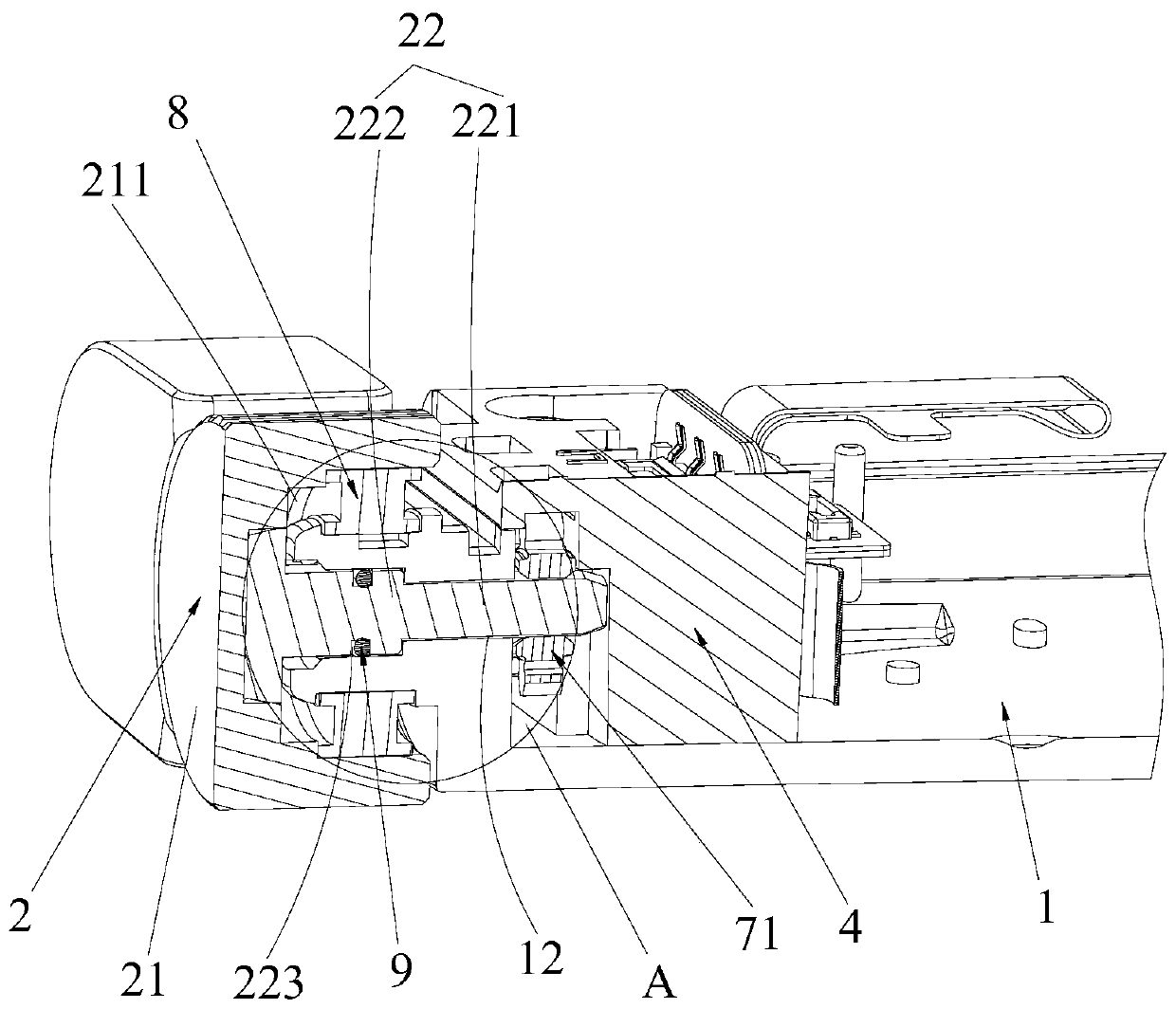
[0054] Further, see Figure 3-Figure 4 , as another specific embodiment of the earphone control structure provided by the present application, the mounting bracket 1 is provided with a rotating mounting cylinder 13 surrounding the rotating hole 12 at the opening of the rotating hole 12; One side of device 3; The outer wall of rotating mounting cylinder 13 is equipped with bearing 8, and the inner ring of bearing 8 links to each other with rotating mounting cylinder 13, and screw cap 21 links to each other with the outer ring of bearing 8. The bearing 8 can make the screw cap 21 only rotate after being stressed, and then drive the rotating shaft 22 to only rotate. The bearing 8 can improve the rotation stability of the screw cap 21; The direct contact between parts avoids the loss of products caused by friction between parts during rotation, and improves the service life of products.

[0055] Further, see Figure 3-Figure 4 , as another specific implementation of the earphone...


PUM


Abstract

The invention discloses an earphone control structure. The earphone control structure comprises a mounting frame, a knob which is rotationally mounted on the mounting frame, and an encoder which is used for identifying a rotating state of the knob so as to realize switching of the working state of an earphone. A user rotates the knob to enable the knob to rotate relative to the mounting frame, andthe encoder is directly triggered or triggered through other transmission components when the knob rotates; the encoder can identify the rotating state of the knob, and then the earphone is switchedto the corresponding working state. Compared with a mode in the prior art that keys are matched with a microswitch and needs to be pressed for multiple times, and the keys are spaced according to certain requirements, the working state of the earphone can be conveniently adjusted, and great convenience is brought to a user.

Description

technical field [0001] The present application relates to the field of earphone equipment, in particular to an earphone control structure. Background technique [0002] The earphone has developed from a simple sound playing device to an electronic device with multiple modes, which can be switched between various functions. The existing switching method is to press the button with the micro switch, and switch between the multi-functions by pressing the finger. When operating, the same action is repeated many times, and the switching is achieved according to the number of actions, interval time or pressing time. In the desired working state, the action time is long, error-prone, and poor in accuracy, resulting in poor user experience. Contents of the invention [0003] The purpose of the present application is to provide an earphone control structure, which aims to solve the problem of inconvenient switching between different working states of the earphone in the prior art....

Claims


Application Information

Patent Timeline
Patent Type & Authority Applications(China)
IPC IPC(8): H04R1/10
CPCH04R1/1041H04R2201/10
Inventor 韩峰熊友军
Owner UBTECH ROBOTICS CORP LTD
Why Eureka
Try Eureka