An adjustable component pin bending and shearing integrated device

A component and adjustable technology, applied in the field of adjustable component pin bending and shearing integrated devices, can solve the problems of inability to meet the bending and shearing requirements of different components, inability to achieve continuous operation, and small scope of application, To achieve the effect of simple and fast processing procedures, wide application range and improved efficiency

Active Publication Date: 2021-07-13
临沂市汇川电子科技有限公司
View PDF9 Cites 0 Cited by
  • Summary
  • Abstract
  • Description
  • Claims
  • Application Information

AI Technical Summary

Problems solved by technology

[0004] In order to overcome the shortcomings of the existing technology that cannot meet the bending and shearing requirements of different components, the scope of application is small, continuous operation cannot be realized, and the work efficiency is low, the technical problem of the present invention is to provide a Bending and cutting for different lengths of pins, an adjustable component pin bending and cutting integrated device with high work efficiency

Method used


Image

  • An adjustable component pin bending and shearing integrated device
  • An adjustable component pin bending and shearing integrated device
  • An adjustable component pin bending and shearing integrated device

Examples


Embodiment 1

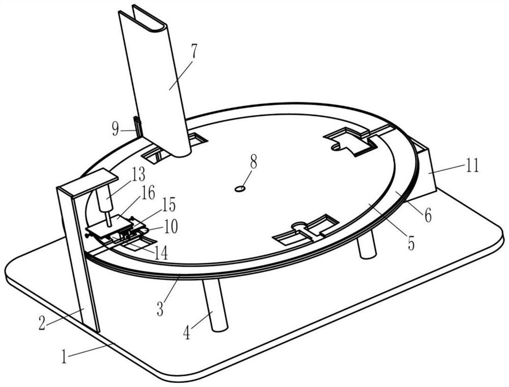
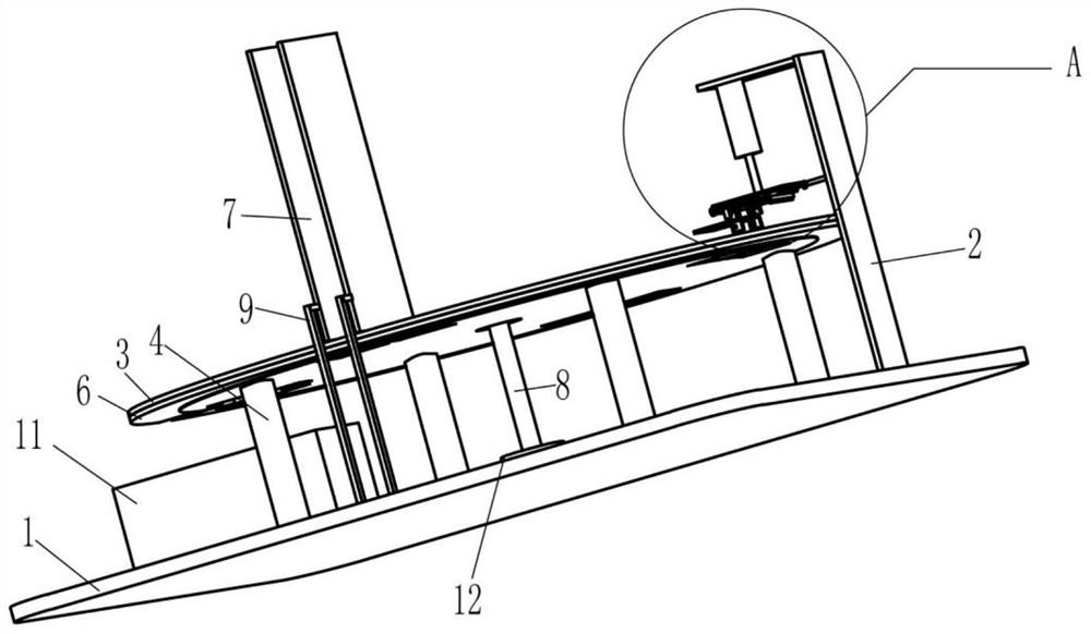
[0024] An adjustable component pin bending and shearing integrated device, such as figure 1 As shown, it includes a base 1, a support arm 2, a limit ring 3, a column 4, a rotating disk 5, a fixed disk 6, a component tank 7, a rotating shaft 8, a support rod 9, a collection tank 11, and a bearing 12. Cylinder 13, shearing part 14 and mounting plate one 16, four uprights 4 are fixedly installed on the base 1, fixed discs 6 are fixedly installed on the upper ends of the four uprights 4, and the fixed discs 6 The upper side is provided with a limit ring 3, and the middle position of the upper side of the base 1 is fixedly equipped with a bearing one 12, and the rotating shaft one 8 is connected through an interference in the bearing one 12, and a middle position of the fixed disk 6 is provided with a The upper end of the through hole and the rotating shaft 8 passing through the through hole is provided with a rotating disk 5, the rotating disk 5 is located above the fixed disk 6, ...

Embodiment 2

[0029] An adjustable component pin bending and shearing integrated device, such as figure 1As shown, it includes a base 1, a support arm 2, a limit ring 3, a column 4, a rotating disk 5, a fixed disk 6, components 10, a tank 7, a rotating shaft 8, a support rod 9, a collection tank 11, Bearing one 12, cylinder 13, shearing part 14 and mounting plate one 16, described base 1 is fixedly installed with 4 uprights 4, and the upper end of 4 described uprights 4 is fixedly installed with fixed plate 6, and described fixed plate The upper side of 6 is provided with a limit ring 3, and the middle position of the upper side of the base 1 is fixedly equipped with a bearing 12, and the rotating shaft 8 is connected through the interference in the bearing 12, and the middle position of the fixed disk 6 A through hole is provided and the upper end of the rotating shaft 8 passing through the through hole is provided with a rotating disk 5, the rotating disk 5 is located above the fixed disk...


PUM


Abstract

The invention relates to the technical field of component pin bending and shearing, in particular to an adjustable component pin bending and shearing integrated device. The technical problem of the present invention is to provide an adjustable component pin bending and cutting integrated device that can meet the needs of bending different positions of components and cutting different lengths of pins, and has high working efficiency. The technical solution of the present invention is: an adjustable component pin bending and shearing integrated device, including a base, a support arm, a limit ring, a column, a rotating disc, a fixed disc, a component tank, etc.; the base A plurality of uprights are installed on the top, and one end of the plurality of uprights is provided with a fixed plate. The present invention can realize the integrated bending and shearing processing operation of components through the cooperation of shearing parts and bending parts. The processing procedure is simple and fast, and the bending position and shearing length of components can be adjusted. wide.

Description

technical field [0001] The invention relates to the technical field of component pin bending, in particular to an adjustable component pin bending and shearing integrated device. Background technique [0002] Electronic components are components of electronic components and small machines and instruments. They are often composed of several parts and can be used in similar products. They often refer to certain parts in industries such as electrical appliances, radios, and instruments. The bending and shearing operation is a common processing operation. The components that have been bent and sheared are beneficial to the subsequent welding process and facilitate subsequent processing operations. [0003] Although the existing component bending and shearing technology equipment can perform integrated bending and shearing operations on components, it cannot adjust the position where components need to be bent and the length that component pins need to cut, and cannot meet differ...

Claims


Application Information

Patent Timeline
Patent Type & Authority Patents(China)
IPC IPC(8): B21F1/00B21F11/00
CPCB21F1/00B21F11/00
Inventor 刘江南
Owner 临沂市汇川电子科技有限公司
Why Eureka
Try Eureka